
Friction stir welding device capable of removing welding holes

A friction stir and welding device technology, applied in welding equipment, non-electric welding equipment, metal processing equipment, etc., can solve the problems of unsightly materials, welding holes cannot be effectively removed, etc., and achieve the effect of avoiding displacement

Pending Publication Date: 2021-06-04
熊有子
View PDF5 Cites 0 Cited by
  • Summary
  • Abstract
  • Description
  • Claims
  • Application Information

AI Technical Summary

Problems solved by technology

[0003] In the traditional friction stir welding technology, the welding seam is welded by continuous friction between the high-speed rotating welding tool and the workpiece. After the weld seam is welded, the friction welding head is still rotating at high speed. Pores cannot be effectively removed, making the finished material unattractive

Method used


Image

  • Friction stir welding device capable of removing welding holes
  • Friction stir welding device capable of removing welding holes
  • Friction stir welding device capable of removing welding holes

Examples


Embodiment 1

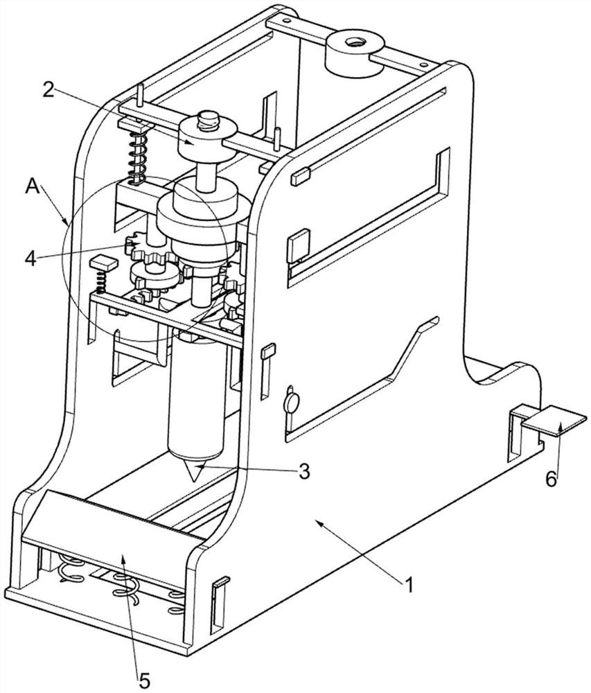
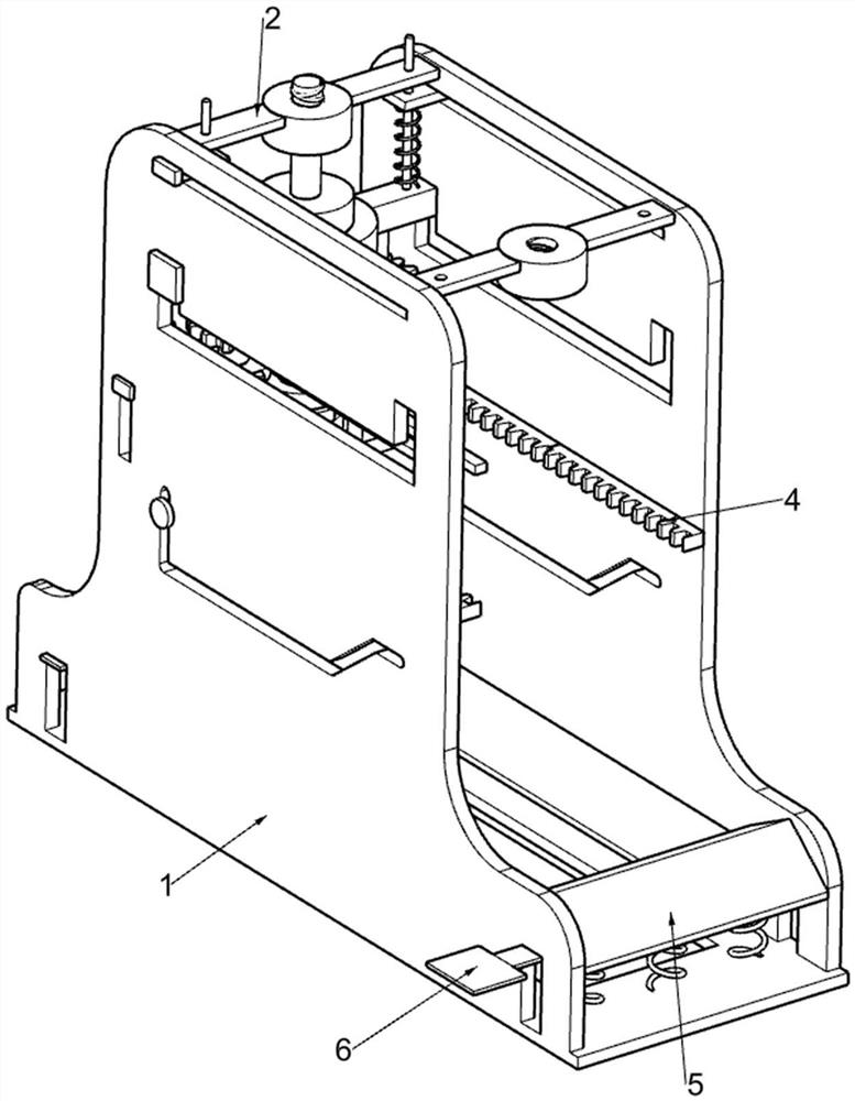
[0024] A friction stir welding device that removes weld holes, such as Figure 1-7 As shown, it includes a support frame 1, a rotating mechanism 2, a drilling mechanism 3, a moving mechanism 4 and a clamping mechanism 5. The drilling mechanism 3, the moving mechanism 4 are arranged on the rotating mechanism 2, and the clamping mechanism 5 for clamping the metal material plate is arranged on the support frame 1.

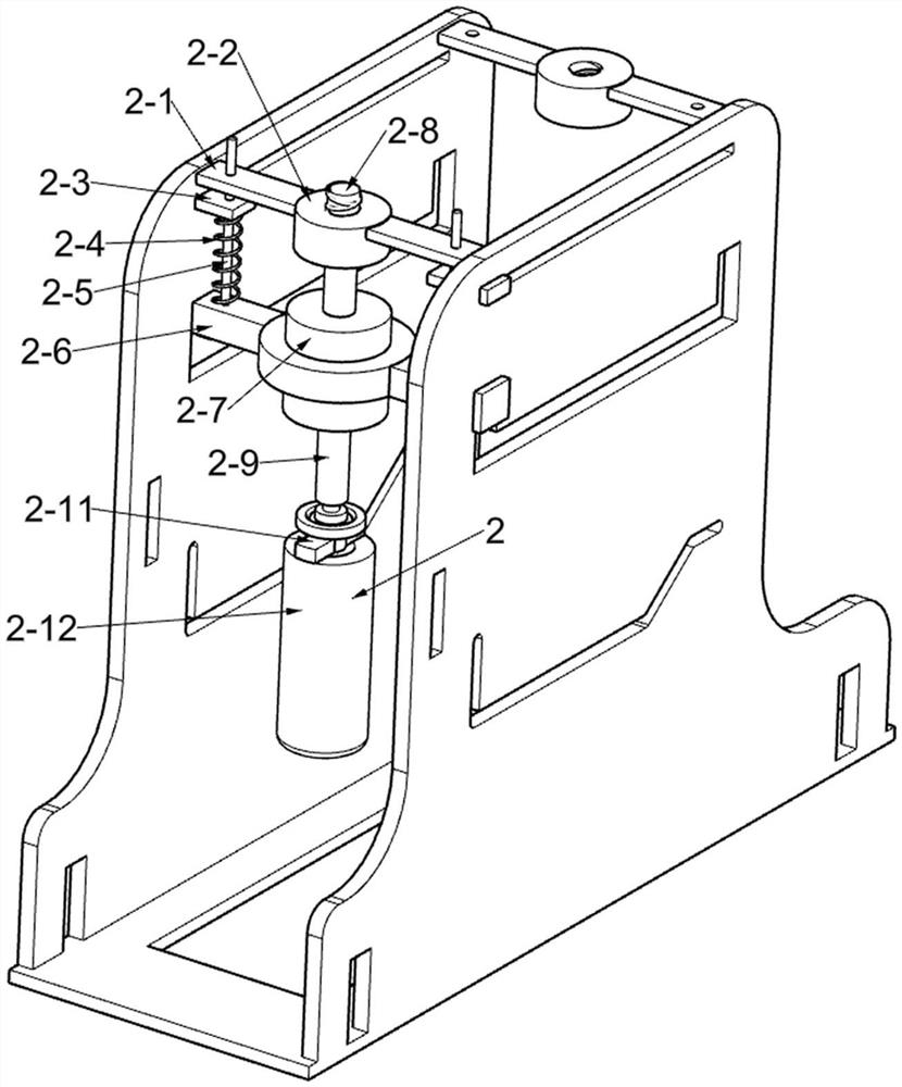
[0025] Turning mechanism 2 includes fixed plate 2-1, fixed nut 2-2, sliding plate 2-3, first return spring 2-4, slide bar 2-5, first sliding frame 2-6, two-way motor 2-7 , two-way screw rod 2-8, rotating shaft 2-9, first fixed block 2-11 and grinding disc 2-12, two fixed plates 2-1 are fixed symmetrically on the inner side of support frame 1, away from the two fixed plates 2 of support frame 1 -1 is jointly fixed with a fixed nut 2-2, two sliding plates 2-3 are slidably connected on the support frame 1 close to the fixed plate 2-1, and a slide bar 2-5 is slidably con...

Embodiment 2

[0033] On the basis of Example 1, such as Figure 7 Shown, also include pedal 6, one side away from the wedge-shaped plate 5-2 of sliding block 5-3 is fixedly connected with the pedal 6 that is convenient to take out metal material plate, and pedal 6 slides with support frame 1 formula fit.

[0034] After polishing, the user steps down on the pedal 6 to drive the wedge-shaped plate 5-2 to move downward, so that the staff can take out the welded metal material plate from the fixed support plate 5-4.


PUM


Abstract

The invention relates to the field of friction stir welding, in particular to a friction stir welding device capable of removing welding holes. The friction stirring welding device comprises a support frame, a rotating mechanism, a drilling mechanism, a moving mechanism and the like, wherein the rotating mechanism is arranged on the support frame; the drilling mechanism is arranged on the rotating mechanism; and the moving mechanism is arranged on the rotating mechanism. Through arrangement of the drilling mechanism and the moving mechanism, a friction welding head rapidly rotates to drill metal material plates, a first sliding frame and a device thereon slowly move in the direction away from a third sliding frame, and the friction welding head rapidly rotates and slowly moves in the direction away from the third sliding frame, so that welding seams of the two metal material plates are fully welded, and excessive welding holes are prevented from being formed in the metal material plates by the friction welding head.

Description

technical field [0001] The invention relates to the field of friction stir welding, in particular to a friction stir welding device capable of removing welding holes. Background technique [0002] Friction stir welding refers to the use of heat generated by the friction between the high-speed rotating welding tool and the workpiece to locally plasticize the welded material. When the welding tool moves forward along the welding interface, the plasticized material acts on the rotational friction of the welding tool It flows from the front of the welding tool to the rear, and forms a dense solid-phase weld under the extrusion of the welding tool. The main materials connected by friction stir welding are lead, zinc, copper, stainless steel, low carbon steel, etc. Material. [0003] In the traditional friction stir welding technology, the welding seam is welded by continuous friction between the high-speed rotating welding tool and the workpiece. After the weld seam is welded, t...

Claims


Application Information

Patent Timeline
Patent Type & Authority Applications(China)
IPC IPC(8): B23K20/12
CPCB23K20/125B23K20/126
Inventor 熊有子
Owner 熊有子
Learn More