
Helicopter rotor maintenance and detection device for aviation industry

A helicopter rotor and detection device technology, applied in the field of aviation maintenance, can solve the problems of inconvenient inspection and inspection of the rotor, lower inspection efficiency, time-consuming and laborious replacement of the rotor rubber strip, etc.

Active Publication Date: 2021-06-04
辽宁航星设备制造有限公司
View PDF5 Cites 0 Cited by
  • Summary
  • Abstract
  • Description
  • Claims
  • Application Information

AI Technical Summary

Problems solved by technology

[0005] In order to solve the above-mentioned technical problems, the present invention provides a helicopter rotor maintenance detection device for the aviation industry, to solve the problem that the inspection of the rotor is inconvenient due to the influence of the terrain during the daily maintenance and inspection of machinery, and the time-consuming and labor-intensive replacement of the rotor rubber strip reduces the inspection efficiency. question

Method used


Image

  • Helicopter rotor maintenance and detection device for aviation industry
  • Helicopter rotor maintenance and detection device for aviation industry
  • Helicopter rotor maintenance and detection device for aviation industry

Examples


Embodiment

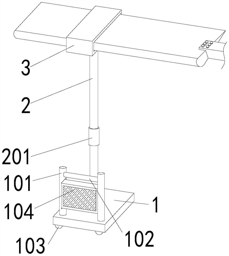
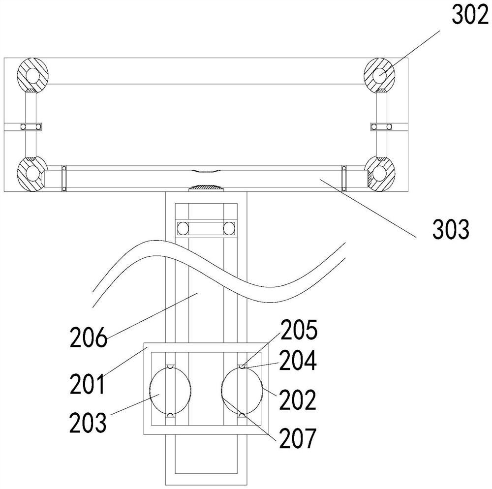
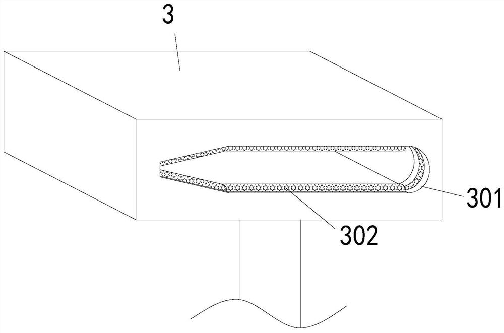
[0031] as attached figure 1 to attach Figure 8 Shown: a helicopter rotor maintenance detection device for the aviation industry, including a base 1, a support rod 2, and a detection device 3, wherein the support rod 2 is movably connected to the center of the top of the base 1, and the middle and lower parts of the support rod 2 are equipped with a drive Device 201, while the detection device 3 is movably connected to the top of the pole 2, the inner bearing of the pole 2 is connected to the driving rod 206, and the middle and lower section of the shaft of the driving rod 206 is provided with an engaging groove 207, and the inner walls of the two sides of the driving device 201 are provided with There is a driving ball groove 202, and a driving ball 203 is meshed and connected to the driving ball groove 202. The driving ball 203 extends to the inside of the pole 2 and engages with the engaging groove 207. The driving ball 203 penetrates the upper ends of the pole 2. A ball g...

Embodiment 2

[0045] When it is necessary to attach the rotor rubber strip to the windward side of the rotor, when the rubber strip in the right side plate 306 in the detection device 3 reaches the expected attachment position with the rotating shaft 324, the driving device 201 on the pole 2 is twisted, and the At this time, the internal drive ball 203 will rotate in the drive ball groove 202, and at the same time drive the drive rod 206 to rotate. At this time, the drive rod 206 will drive the drive shaft at the bottom of the right side plate 306 to rotate. When the drive shaft rotates, it will drive the rubber strip to take The rotating shaft 324 rotates, so that the rubber strip roll 323 engaged with the rubber strip taking rotating shaft 324 rotates, and at the same time, the rubber strip on the rubber strip rolling 323 is taken out under the action of the rotating shaft 324 and attached to the windward surface of the rotor. With the movement of the detection device 3, the rotor with the...


PUM


Abstract

The invention provides a helicopter rotor maintenance detection device for an aviation industry, which comprises a base, a support rod and a detection device, the center of the top of the base is movably connected with the support rod, the middle lower section of the support rod body is provided with a driving device, the top of the support rod is movably connected with the detection device, and a bearing in the support rod is connected with a driving rod. A meshing groove is formed in the lower middle section of a rod body of the driving rod, driving ball grooves are formed in the inner walls of the two sides of the interior of the driving device, driving balls are connected into the driving ball grooves in a meshing mode, the driving balls extend into the supporting rods and are meshed with the meshing groove, fixing ball grooves are formed in the two upper ends, penetrating through the supporting rods, of the driving balls, and fixing balls are movably connected into the fixing ball grooves; the invention provides the helicopter rotor maintenance and detection device for the aviation industry in order to solve the problems that during daily maintenance and detection of machinery, rotor detection is not convenient due to the influence of terrains, replacement of rotor rubber strips wastes time and labor, and the detection efficiency is reduced.

Description

technical field [0001] The invention relates to the technical field of aviation maintenance, in particular to a helicopter rotor maintenance detection device for the aviation industry. Background technique [0002] The rotor is an important part of the helicopter. During the flight of the helicopter, the rotor plays the dual role of generating lift and pulling force. When the helicopter takes off and lands, a strong annular airflow will be generated to drag dust and other debris from the ground into the rotor and collide with the windward side of the rotor to cause damage to the rotor. . [0003] Therefore, most of the rotors are now attached to the windward side with rotor rubber strips to protect the windward side of the rotor, prevent the windward damage of the rotor, reduce the service life of the rotor, strengthen the anti-collision ability of the rotor, and improve flight safety. [0004] However, there is no corresponding equipment for the replacement of rotor rubbe...

Claims


Application Information

Patent Timeline
Patent Type & Authority Applications(China)
IPC IPC(8): B64F5/60B64F5/40
CPCB64F5/60B64F5/40
Inventor 柳维朋
Owner 辽宁航星设备制造有限公司
Learn More