
Chain belt-type variable transmission

A continuously variable transmission, chain-belt type technology, applied to components with teeth, belts/chains/gears, mechanical equipment, etc., can solve problems such as sliding, vibration and noise, and inability to transmit power to expand the contact area , Reduce vibration and noise, reduce vibration and noise effect

Inactive Publication Date: 2013-09-04
赵闰奎
View PDF5 Cites 8 Cited by
  • Summary
  • Abstract
  • Description
  • Claims
  • Application Information

AI Technical Summary

Problems solved by technology

[0004] However, this structure transmits power in only one direction, so when driving downhill or using the engine brake, there is a problem that power cannot be transmitted and slippage occurs
[0005] In addition, the chain belt holder provided in the transmission of the conventional invention is horizontally installed in a state parallel to the pulley shaft, and when the chain belt is wound around the outside of such a plurality of chain belt holders and rotates, the chain belt holder and the belt holder During the contact and separation process of the chain belt, there will be problems of vibration and noise

Method used


Image

  • Chain belt-type variable transmission
  • Chain belt-type variable transmission
  • Chain belt-type variable transmission

Examples


Embodiment Construction

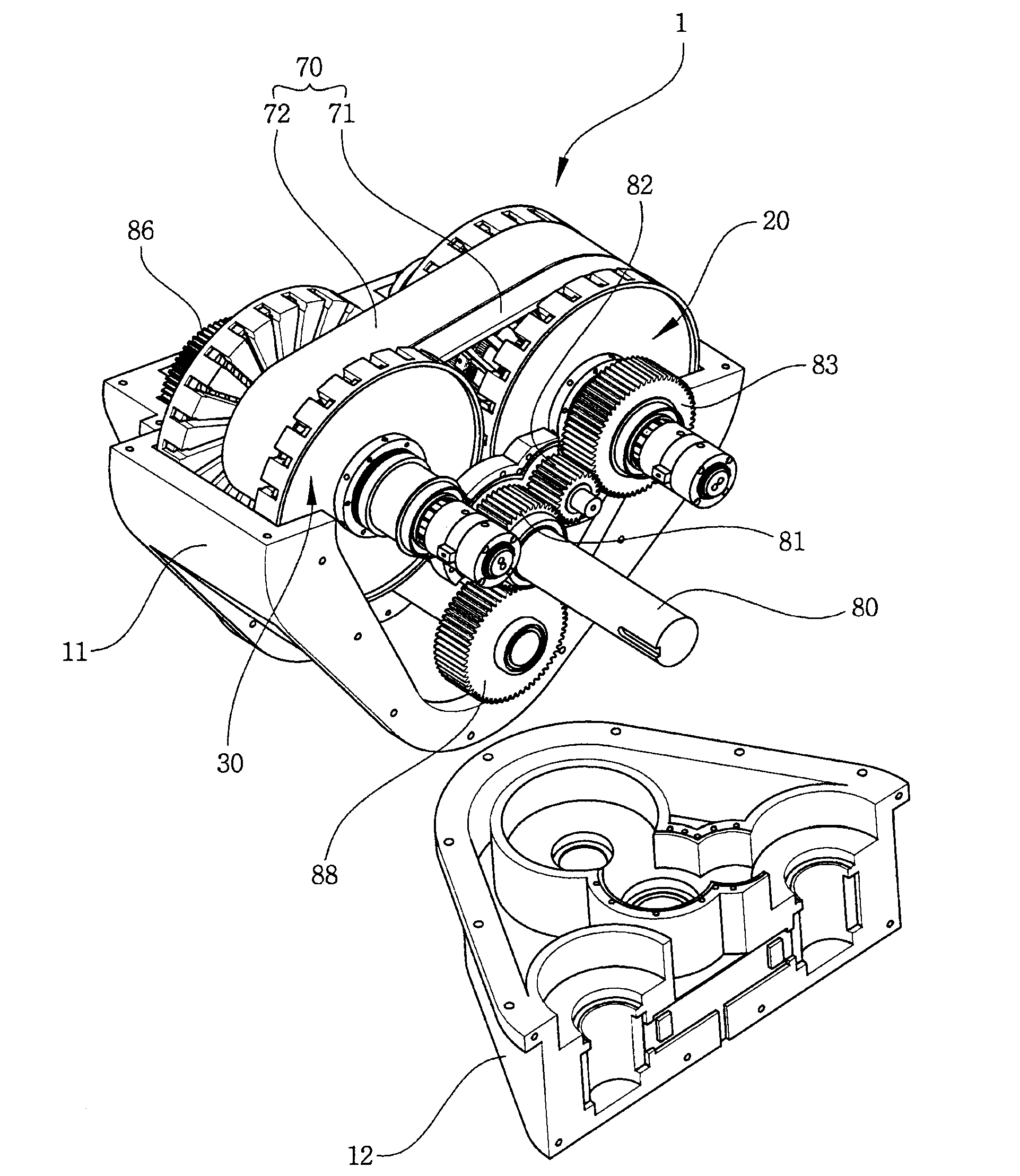
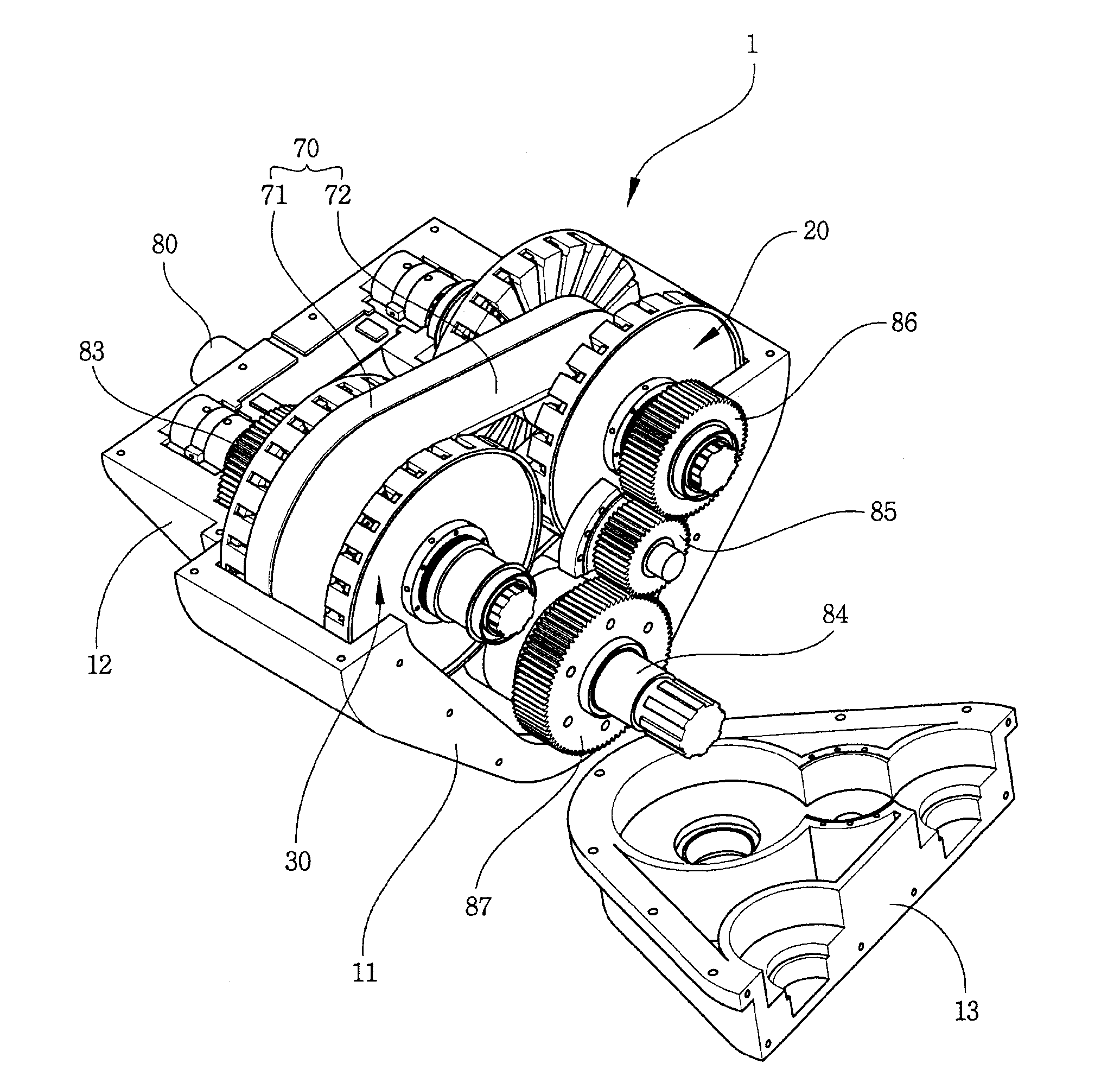
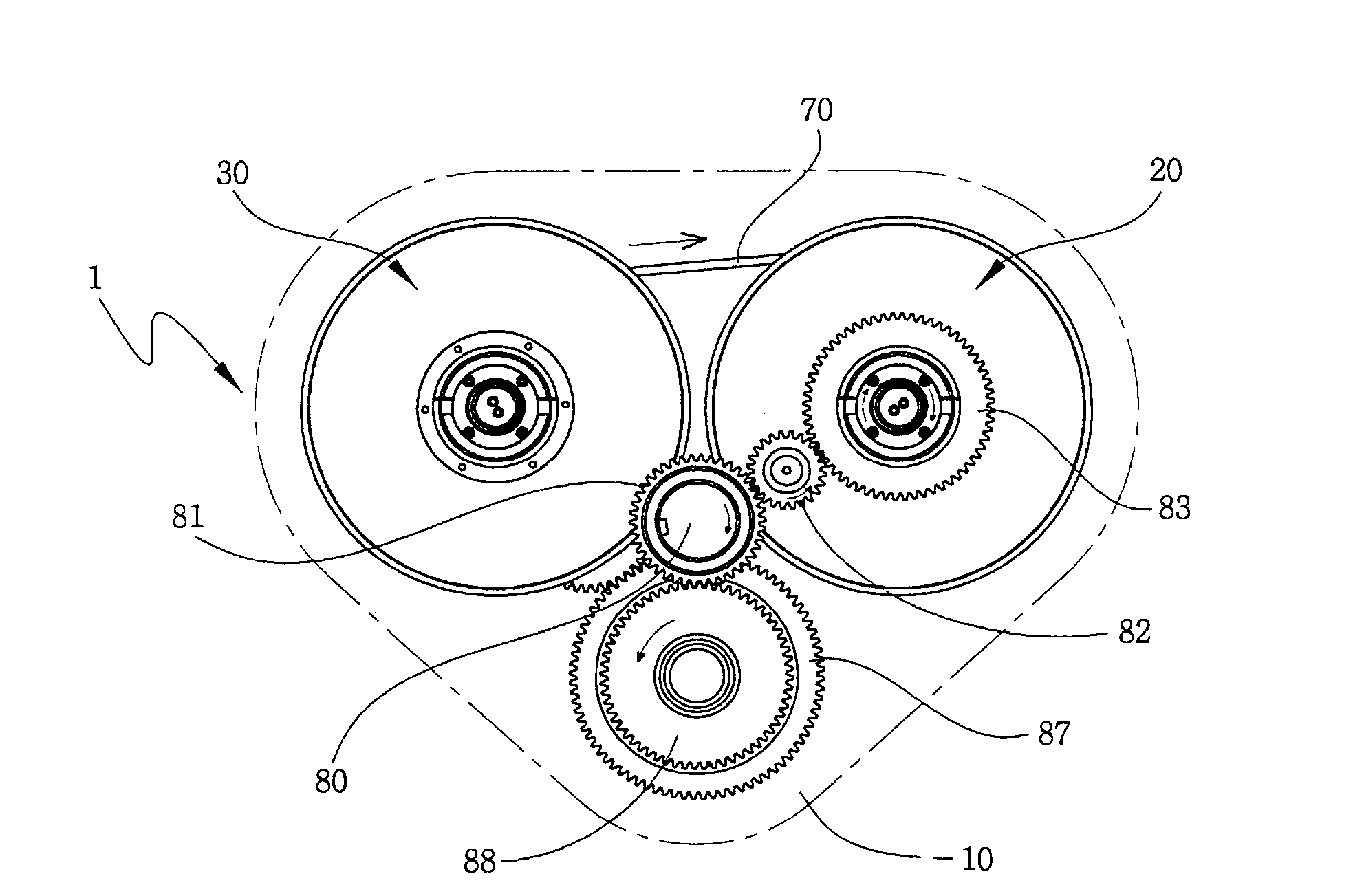
[0035] Below, refer to the attached Figure 1 to Figure 19 , the chain-belt type continuously variable transmission of the present invention will be described as follows.

[0036] figure 1 and figure 2It is a drawing showing a chain-belt type continuously variable transmission according to the present invention, and is a diagram showing a disassembled state in which each front case 12 and rear case 13 are exposed while omitting the illustration of the upper case and showing the gear connection mechanism of the power transmission process. The illustrated front perspective view and rear perspective view, while Figure 8 will be figure 1 The illustrated bottom perspective view of the illustrated transmission body 2 rotated 180 degrees in the clockwise direction.

[0037] This type of chain-belt type continuously variable transmission 1 based on the present invention is as figure 1 , figure 2 and Figure 8 As shown, it is composed of a case and a transmission body 2. The ...


PUM


Abstract

The present invention relates to a chain belt-type variable transmission for controlling a transmission gear ratio, in which a chain belt is wound to a driving pulley device and to a driven pulley device having variable diameters, and more particularly, in which the tooth profile of front and rear latch gear portions are formed in opposite directions while the latch gear portions are divided into front and rear portions, and are formed on a plurality of driving side belt supports and driven side belt supports, each of which is radially and expandably installed on the driving pulley device and the driven pulley device so as to have a predetermined distance therebetween, wherein each of the latch gear portions that are formed on the driving belt support and each of the tooth profiles of the latch gear portions that are formed on the driven side belt support face opposite sides,; so that each of the latch gear portions that is formed on the driving side belt support and on the driven side belt support is installed so as to crisscross and not be on one line, and wherein two strips of latch-type chain belts that correspond to the front and rear latch gear portions are wound on the driving pulley device and the driven pulley device for transferring driving force from the driving and the driven sides in both directions, and the plurality of driving side belt supports and the driven side belt supports, which are installed on the driving pulley device and the driven pulley device are installed obliquely like a tooth profile of a helical gear,; for reducing noise when the latch-type chain belt and the belt supports contact and separate from each other while increasing the contact area between the latch gear portions of the belt supports and the latch portion of the latch-type chain belt to provide more accurate transferring of driving force.

Description

technical field [0001] The present invention relates to a chain-belt type continuously variable transmission, which is provided with a latch-type chain belt wound around a variable-diameter driving pulley device and a driven pulley device, for controlling a speed change ratio, and more specifically, between a driving pulley device and a driven pulley device In the driven pulley device, a plurality of driving side chain belt brackets that are arranged radially and flexibly at predetermined intervals and a lock pin mechanism part formed on the driven side chain bracket are divided into front and rear, and the front and rear sides are locked. The tooth shape of the pin mechanism part is formed in the opposite direction, and the tooth shape of each latch mechanism part formed on the drive side chain belt bracket and each lock pin mechanism part formed on the driven side chain belt bracket is in the opposite direction, so that the The plurality of lock pin mechanism parts formed by...

Claims


Application Information

Patent Timeline
Patent Type & Authority Applications(China)
IPC IPC(8): F16H37/02F16H9/12
CPCF16H9/24F16H37/0846F16H55/54F16H63/065F16H63/067
Inventor 赵闰奎
Owner 赵闰奎
Learn More