Adjustable inserting piece for ceiling joist and connecting structure of adjustable inserting piece
A technology for connecting structures and plug-ins, which is applied in the direction of ceilings, building components, building structures, etc., and can solve problems such as easy sliding, unstable connection, and inability to adjust the width and height of the keel frame
- Summary
- Abstract
- Description
- Claims
- Application Information
AI Technical Summary
Problems solved by technology
Method used
Image
Examples
Embodiment 1
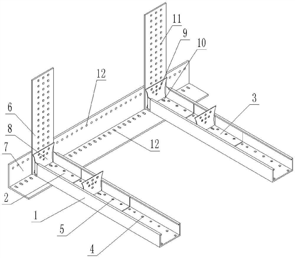
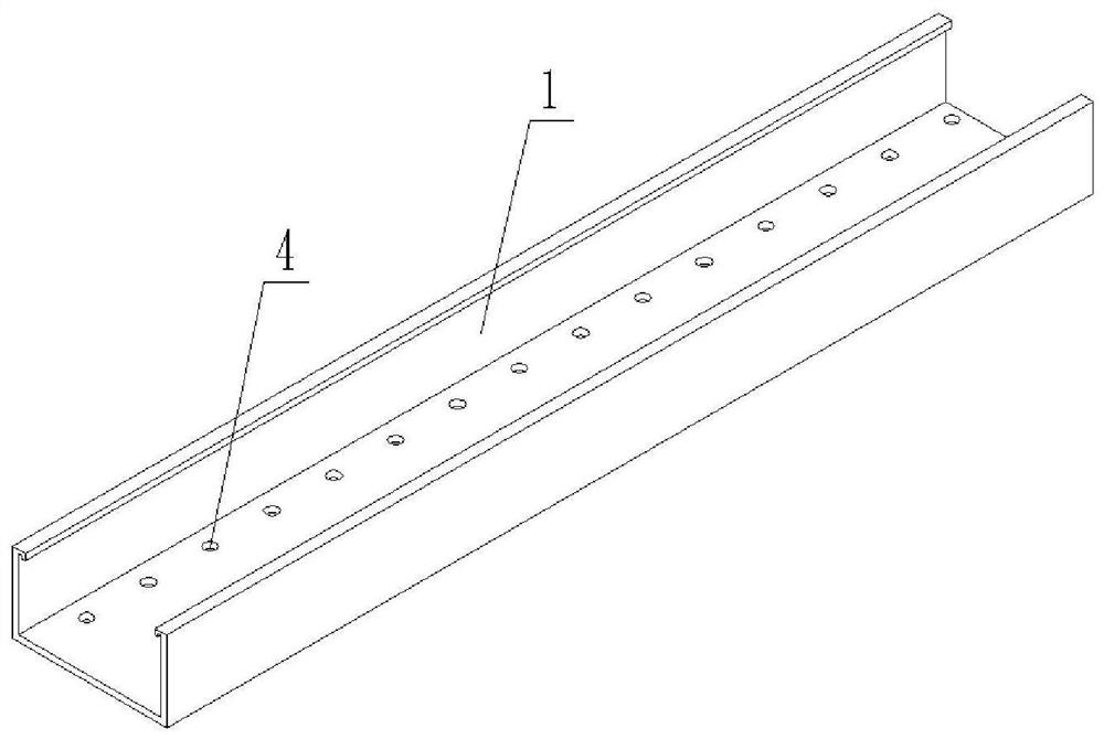
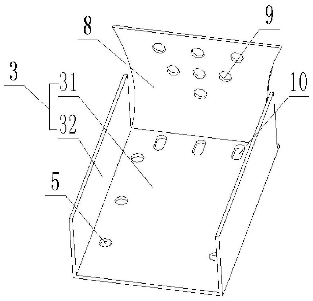
[0069] The present invention is specifically described below in conjunction with accompanying drawing, as Figure 1-Figure 5 As shown, an adjustable plug-in for a ceiling joist and its connection structure, including a horizontal joist 1, an adjustable plug-in 2, a vertical joist 6, and an angle joist 7. In order to facilitate the installation of the horizontal joist 1 and the vertical joist 6, the Adjustable plug-in 2 is installed at the connection between the two ends of the vertical keel and the vertical keel 6. The adjustable plug-in 2 is made of one-piece molding. The efficiency of producing the adjustable plug-in 2 in this way is high. 1 can also be installed in the middle of the horizontal keel 1, so that the vertical keel 6 and the horizontal keel 1 can form many shapes and structures, such as: L-shaped, U-shaped, π-shaped, F-shaped, when installed on the horizontal keel 1 at the end position, the lateral width of the keel frame can be adjusted by pulling the socket 3,...
Embodiment 2
[0080] Reference attached Image 6 , 7 , for the convenience of observation, attach Figure 6-7 The black circle in the circle is the second-order adjustment hole 5, and the empty circle is the first-order adjustment hole 4. Figure 7 This is the state where the first hole in the first column on the left of the second-order adjustment hole 5 and the first hole in the first column on the left of the first-order adjustment hole 4 overlap. The figure is only for the convenience of explaining the principle, and only part of the adjustment holes are drawn.
[0081]The difference between this embodiment and Embodiment 1 is that each row of holes of the second-order adjustment holes 5 provided on the plug-in 2 is distributed in a vertical dislocation, the first-order adjustment holes 4 are distributed in a rectangular array, and the highest row of holes in all the rows of second-order adjustment holes 5 is to The longitudinal misalignment values of the lowest column are H / N, 2H / ...
Embodiment 3
[0085] Reference attached Figure 8 , 9 , with Figure 9 This is the state where the first hole in the first column on the left of the second-order adjustment hole 5 and the first hole in the first column on the left of the first-order adjustment hole 4 overlap. The figure is only for the convenience of explaining the principle, and only part of the adjustment holes are drawn.
[0086] The difference between this embodiment and Embodiment 1 and Implementation 2 is that the first-order adjustment holes 4 and the second-order adjustment holes 5 are in a row, and at this time, the distance between two adjacent holes in each row of holes in the second-order adjustment holes 5 and a A fixed difference is set for the distance between two adjacent holes in each column of hole 4. The fixed difference is H÷M*X, X is a positive integer and the value is 1, and the fixed difference is H÷M. The fixed difference is based on the number of the second-order adjustment holes 5 to achieve a o...
PUM
 Abstract
Description
Claims
Application Information
 - R&D
- Intellectual Property
- Life Sciences
- Materials
- Tech Scout
- Unparalleled Data Quality
- Higher Quality Content
- 60% Fewer Hallucinations
Browse by: Latest US Patents, China's latest patents, Technical Efficacy Thesaurus, Application Domain, Technology Topic, Popular Technical Reports.
© 2025 PatSnap. All rights reserved.Legal|Privacy policy|Modern Slavery Act Transparency Statement|Sitemap|About US| Contact US: help@patsnap.com


