Scroll plate assembly, scroll compressor and air conditioner

A technology of scroll compressors and scroll disks, which is applied in the field of compressors and can solve problems affecting the energy efficiency of scroll compressors, gas flow loss, etc.

Pending Publication Date: 2021-06-04
ANHUI MEIZHI PRECISION MFG
View PDF0 Cites 2 Cited by
  • Summary
  • Abstract
  • Description
  • Claims
  • Application Information

AI Technical Summary

Problems solved by technology

However, in this scheme, since the pressure of the working chamber changes with the operation of the fixed scroll, when the pressure of the working chamber at the back pressure hole is high, the gas in the working chamber can easily enter the back pressure chamber th

Method used


Image

  • Scroll plate assembly, scroll compressor and air conditioner
  • Scroll plate assembly, scroll compressor and air conditioner
  • Scroll plate assembly, scroll compressor and air conditioner

Examples


Embodiment 1

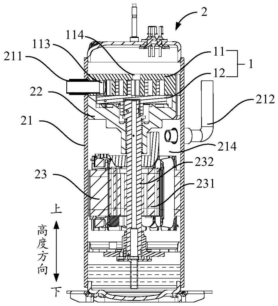
[0077] This embodiment provides a scroll assembly 1 that can be used in a scroll compressor 2 .

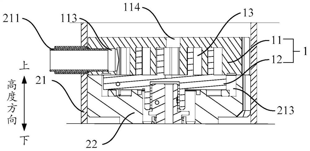
[0078] Such as figure 1 and figure 2As shown, the scroll assembly 1 includes a stationary disk 11 (ie, a fixed scroll) and a moving disk 12 (ie, a movable scroll). The moving disk 12 and the static disk 11 are engaged with each other, and a working chamber 13 is formed between the moving disk 12 and the static disk 11 .

[0079] The moving disk 12 can move in translation relative to the static disk 11 , and during the operation of the moving disk 12 , the shape and volume of the working chamber 13 change dynamically.

[0080] The static disc 11 is provided with an air inlet 113 and an air outlet 114; when assembled in the scroll compressor 2, the air inlet 113 communicates with the air inlet pipe 211 of the scroll compressor 2, and the air outlet 114 communicates with the air inlet pipe 211 of the scroll compressor. The exhaust chamber 214 of 2 communicates.

[0081] During t...

Embodiment 2

[0088] This embodiment provides a scroll assembly 1, which is further improved on the basis of the first embodiment.

[0089] Such as Figure 1 to Figure 4 As shown, as the pressure in the working chamber 13 changes, the oil injection channel 115 communicates with and disconnects with the oil injection groove 123 and the working chamber 13 alternately.

[0090] When the pressure of the working chamber 13 is greater than the pressure of the back pressure chamber 213, the pressure of the working chamber 13 is higher at this time, and the operation of the moving plate 12 disconnects the oil injection channel 115, the oil injection groove 123 and the working chamber 13. To prevent the gas in the working chamber 13 from entering the back pressure chamber 213 through the oil injection channel 115 and the oil injection groove 123, so as to reduce gas loss.

[0091] When the pressure of the working chamber 13 is lower than the pressure of the back pressure chamber 213, the pressure o...

Embodiment 3

[0094] This embodiment provides a scroll assembly 1, which is further improved on the basis of the second embodiment.

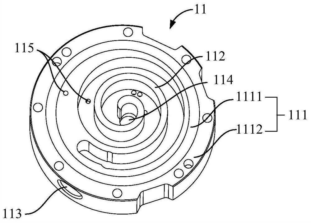
[0095] Such as Figure 1 to Figure 4 As shown, the stationary disk 11 specifically includes a stationary disk end plate 111 (ie, a first end plate) and a stationary disk scroll 112 (ie, a static scroll structure). The static disk scroll 112 is arranged on the bottom surface of the static disk end plate 111 and is arranged in a spiral shape. Exhaust holes 114 are located in the static disk scroll 112 to facilitate exhaust.

[0096] Such as Figure 5 and Figure 6 As shown, the oil injection channel 115 specifically includes an oil injection hole 1151, a connecting hole and a back pressure hole 1153. The back pressure hole 1153 is arranged on the bottom surface of the static disk end plate 111, the oil injection hole 1151 is arranged on the bottom surface of the static disk scroll 112, and the oil injection hole 1151 and the back pressure hole 1153 are blin...


PUM


Abstract

The invention relates to the technical field of compressors, and provides a scroll plate assembly, a scroll compressor and an air conditioner. The scroll plate assembly comprises a static scroll plate, and an air inlet hole, an exhaust hole and an oil injection channel are formed in the static scroll plate. A movable scroll plate is meshed with the static scroll plate, a working chamber is formed between the movable scroll plate and the static scroll plate, an oil injection groove communicated with a back pressure chamber of the scroll compressor is formed in the movable scroll plate, and the movable scroll plate is configured to translate relative to the static scroll plate so as to compress a gas entering the working chamber. The oil injection channel is intermittently communicated with the oil injection groove and the working chamber, so that oil in the back pressure camber is intermittently injected into the working chamber under the action of the pressure difference between the back pressure chamber and the working chamber. According to the technical scheme, the gas in the working chamber can be effectively prevented from leaking to the back pressure chamber, so that the flow loss of the gas is reduced in the working process of the scroll plate assembly, and the scroll compressor is promoted to improve the energy efficiency.

Description

technical field [0001] The present application relates to the technical field of compressors, in particular, to a scroll assembly, a scroll compressor and an air conditioner. Background technique [0002] At present, the pressure of the back pressure chamber of the scroll compressor is an intermediate pressure, and the movable scroll is close to the static scroll under the pressure of the back pressure chamber. If the pressure of the back pressure chamber is too high, the movable scroll and the static scroll The friction loss of the disk bonding surface increases, and the power increases; if the pressure in the back pressure chamber is too small, the movable scroll cannot be smoothly attached to the static scroll, which will easily cause the movable scroll to overturn and cause air leakage , resulting in a decrease in the working capacity of the scroll compressor. In the prior art, by setting a back pressure hole in the working chamber, the back pressure hole communicates w...

Claims


Application Information

Patent Timeline
IPC IPC(8): F04C18/02F04C29/00F04C27/02F24F1/08
CPCF04C18/0215F04C18/0253F04C18/0261F04C27/02F04C29/0035F24F1/08
Inventor 谭琴江波杨志鹏罗承卓胡超奇宋红飞
Owner ANHUI MEIZHI PRECISION MFG
Why Eureka
Try Eureka