Electromagnetic proportional valve, flow valve and hydraulic system

A technology of electromagnetic proportional valve and flow valve, which is applied in fluid pressure actuators, servo motor components, mechanical equipment, etc. It can solve the problem of small current, large driving force of pilot valve core, and easy operation performance affected by load And other issues

Active Publication Date: 2021-06-04
WEICHAI POWER CO LTD +1
View PDF17 Cites 2 Cited by
  • Summary
  • Abstract
  • Description
  • Claims
  • Application Information

AI Technical Summary

Problems solved by technology

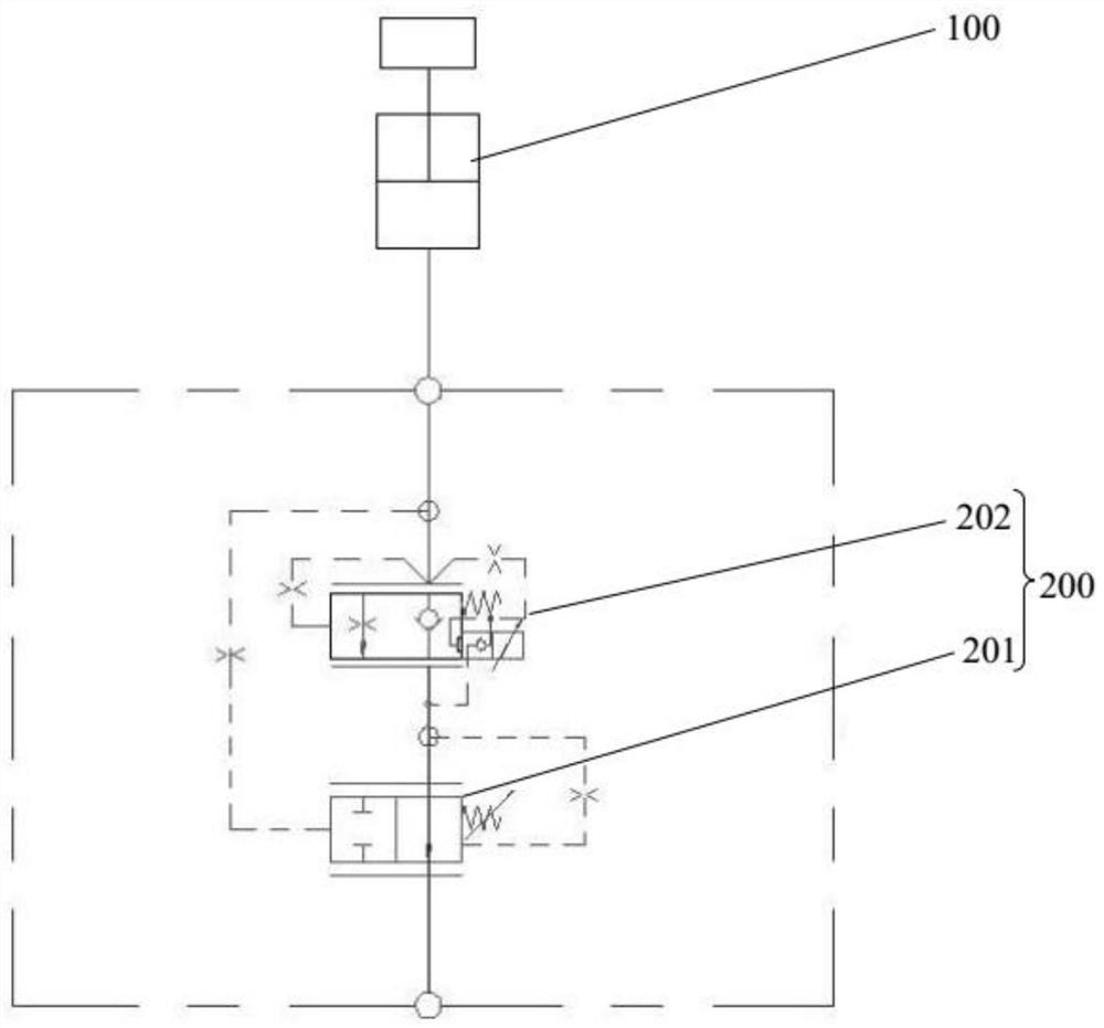
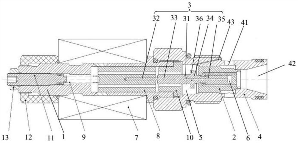
[0004]In the initial operation, after the proportional coil is energized, the armature attracts the pilot spool to move. At this time, the pilot spool is not only affected by the suction force of the armature, but also by the system pressure. Make the initial opening current of the proportional flow valve inconsistent, that is, if the load pressure at port A is large, the driving force on the pilot spool is large, resulting in a larger current, and if the load pressure at port A is small, the driving force on the pilot spool Small, the current becomes smaller, and the initial operation performance is easily affected by the load, which affects the initial operation consistency of the whole machine and has a great impact on the performance of the whole machine

Method used


Image

  • Electromagnetic proportional valve, flow valve and hydraulic system
  • Electromagnetic proportional valve, flow valve and hydraulic system
  • Electromagnetic proportional valve, flow valve and hydraulic system

Examples


Embodiment Construction

[0037] In order to make the technical problems solved by the present invention, the technical solutions adopted and the technical effects achieved clearer, the technical solutions of the embodiments of the present invention will be further described in detail below in conjunction with the accompanying drawings. Obviously, the described embodiments are only the technical solutions of the present invention. Some, but not all, embodiments. Based on the embodiments of the present invention, all other embodiments obtained by those skilled in the art without creative efforts fall within the protection scope of the present invention.

[0038]In the description of the present invention, unless otherwise clearly specified and limited, the terms "connected", "connected" and "fixed" should be understood in a broad sense, for example, it can be a fixed connection, a detachable connection, or an integrated ; It can be a mechanical connection or an electrical connection; it can be a direct ...


PUM


Abstract

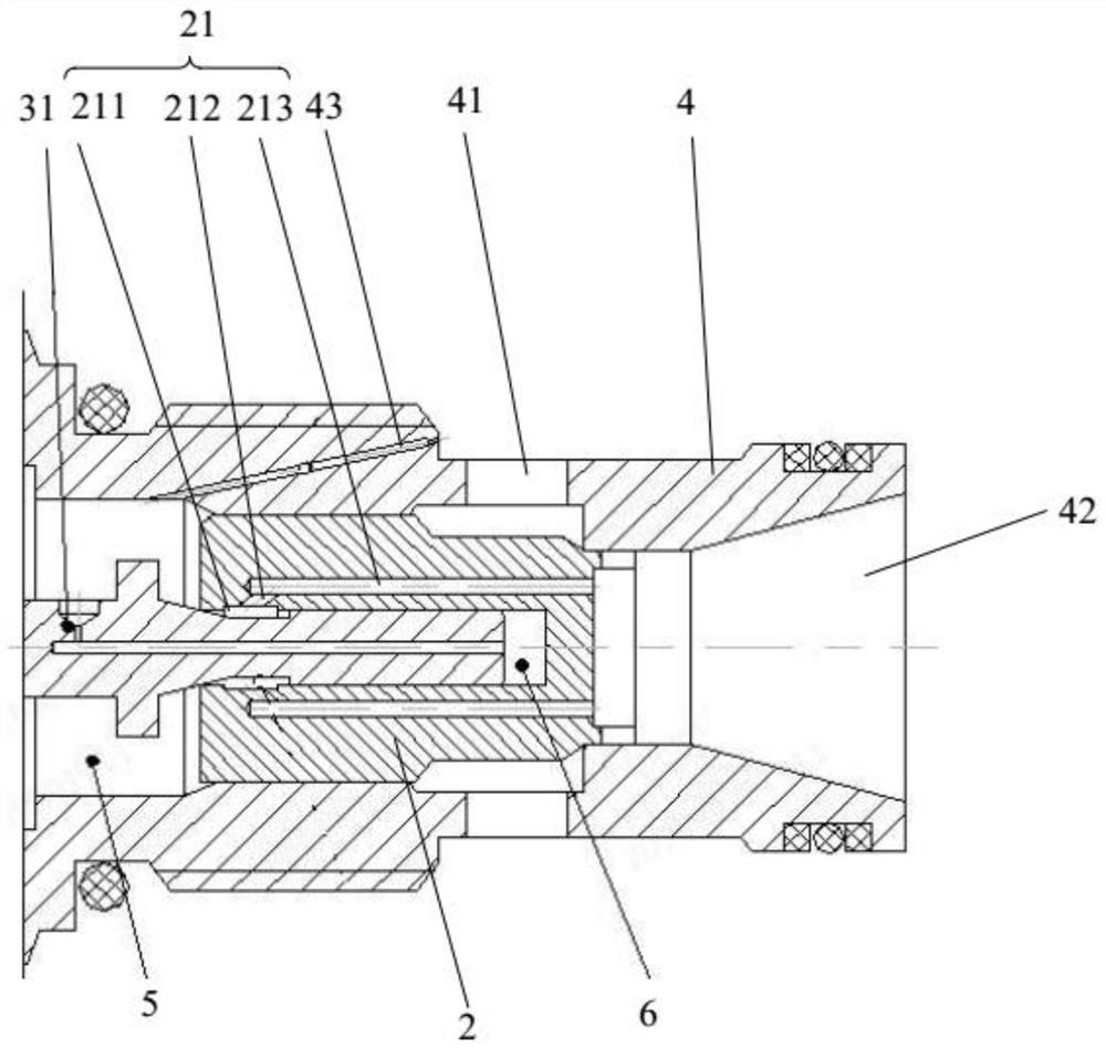
The invention belongs to the technical field of engineering machinery, and discloses an electromagnetic proportional valve, a flow valve and a hydraulic system. According to the electromagnetic proportional valve, a proportional coil is installed on a sleeve, an armature is arranged in the proportional coil in a sliding mode, and a spring is arranged between the armature and the sleeve; a first port and a second port are formed in a valve seat; a main valve element is used for connection and disconnection between the first port and the second port; one end of a pilot valve element penetrates through the armature, the other end of the pilot valve element penetrates through the main valve element in a sliding mode and can abut against a valve port of the main valve element, a first pilot control cavity is formed among the pilot valve element, the main valve element and the valve seat, a second pilot control cavity is formed between the pilot valve element and the main valve element, the first port communicates with the first pilot control cavity, the first pilot control cavity communicates with the second port through a communicating oil channel, and the acting force of hydraulic oil in the first pilot control cavity on the pilot valve element is the same as the acting force of hydraulic oil in the second pilot control cavity on the pilot valve element. The electromagnetic proportional valve is not affected by loads.

Description

technical field [0001] The invention relates to the technical field of engineering machinery, in particular to an electromagnetic proportional valve, a flow valve and a hydraulic system. Background technique [0002] The hydraulic system of the existing construction machinery includes a gravity lowering mechanism, a proportional flow valve and a pressure compensation valve. The proportional flow valve and the pressure compensation valve form a flow valve, which is used to control the descending speed of the gravity lowering, so that the descending speed is only related to the current of the solenoid valve. , and has nothing to do with the load of the gravity lowering mechanism, so that the lowering operation performance can be effectively improved. [0003] The proportional flow valve includes a valve seat, a main valve core, a pilot valve core, a proportional coil, an armature and an adjustment spring. A port and a B port are arranged on the valve seat. The pilot valve core...

Claims


Application Information

Patent Timeline
Patent Type & Authority Applications(China)
IPC IPC(8): F15B13/02
CPCF15B13/021
Inventor 丁坚持任健刘志政徐翊杰
Owner WEICHAI POWER CO LTD
Why Eureka
Try Eureka