Combustion method with pre-combustion chamber burners on the walls on both sides of the boiler

A combustion method and a technology of a pre-combustion chamber, which are applied in the combustion method, combustion using lump fuel and powder fuel, combustion using lump fuel and gaseous fuel, etc., can solve the problems of poor stable combustion ability under low load and high emission , to achieve the effect of increasing the load range and improving the combustion efficiency

Active Publication Date: 2022-02-22
HARBIN INST OF TECH
View PDF10 Cites 0 Cited by
  • Summary
  • Abstract
  • Description
  • Claims
  • Application Information

AI Technical Summary

Problems solved by technology

[0006] In order to solve the problem of poor low-load stable combustion ability and NO x To solve the problem of high emissions, a combustion method with pre-combustion chamber burners on the walls on both sides of the boiler was proposed

Method used


Image

  • Combustion method with pre-combustion chamber burners on the walls on both sides of the boiler
  • Combustion method with pre-combustion chamber burners on the walls on both sides of the boiler
  • Combustion method with pre-combustion chamber burners on the walls on both sides of the boiler

Examples


specific Embodiment approach 1

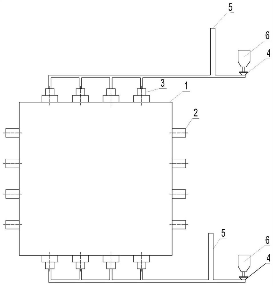
[0026] Specific implementation mode one: combine Figure 1 to Figure 5 To illustrate this embodiment, the combustion system with pre-chamber burners on both sides of the boiler described in this embodiment includes a furnace 1, two sets of main burner mechanisms and two sets of pre-chamber burner mechanisms, and two sets of main burners The mechanism is relatively arranged on the two side walls of the furnace 1, and two sets of pre-chamber burner mechanisms are relatively arranged on the other two walls of the furnace 1.

[0027] The boiler is a power station boiler, specifically an offset coal-fired boiler.

specific Embodiment approach 2

[0028] Specific implementation mode two: combination Figure 1 to Figure 5 Describe this embodiment, each set of pre-chamber burner mechanisms in this embodiment includes a powder feeder 4, a recirculation flue gas pipe 5, a powder storage bin 6 and a plurality of pre-chamber burners 3, and a plurality of pre-chamber burners 3 are The cloth is arranged at the bottom of the side wall of the furnace 1, and the powder outlet end of the powder storage bin 6 is connected with the powder inlet end of the powder feeder 4, and the powder outlet end of the powder feeder 4 is respectively connected with multiple pre-chamber burners 3 through powder feeding pipes , The powder feeding pipe is provided with a recirculation flue gas pipe 5, and the recirculation flue gas pipe 5 is provided with a control valve. The undisclosed technical features in this embodiment are the same as those in the first embodiment.

[0029] The pre-chamber burner 3 is separately connected to the powder feeder 4...

specific Embodiment approach 3

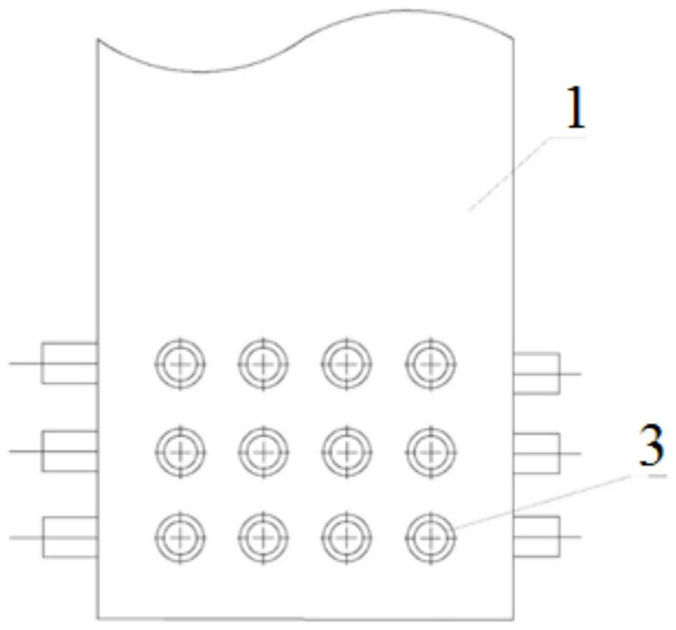
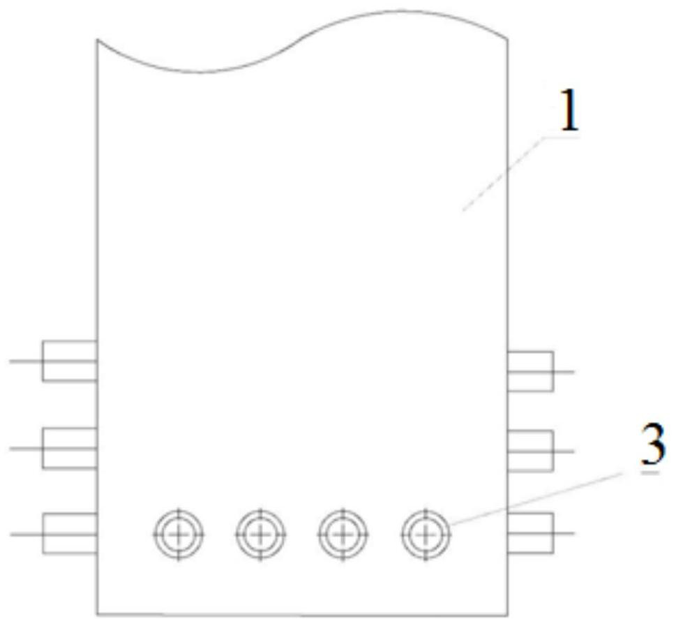
[0031] Specific implementation mode three: combination Figure 1 to Figure 5 Describe this embodiment, a plurality of pre-chamber burners 3 in each group of pre-chamber burner mechanisms in this embodiment are uniformly arranged in n layers, where n is a positive integer, and n layers of pre-chamber burners 3 are arranged from bottom to top They are arranged layer by layer on the side wall of the furnace 1, wherein the lowermost pre-combustion chamber burner 3 is arranged at the bottom of the side wall. The undisclosed technical features in this embodiment are the same as those in the first or second specific embodiment.


PUM


Abstract

The invention relates to a combustion method in which pre-combustion chamber burners are arranged on the two side walls of the boiler, and relates to the technical field of power plant boiler combustion. The invention aims to solve the problem of poor low-load stable combustion ability and NO x The problem of high emissions. The invention comprises a furnace, two sets of main burner mechanisms and two sets of pre-combustion chamber burner mechanisms. On the other side of the wall. The invention is used for power station boilers.

Description

technical field [0001] The invention relates to the technical field of power station boiler combustion, in particular to a combustion method with pre-combustion chamber burners on both sides of the boiler. Background technique [0002] At present, pulverized coal boilers in power stations are still the main source of electricity in China. In the study of China's "14th Five-Year Plan" power development plan, it was proposed that my country should strictly control the new scale of coal power in the eastern and central regions, eliminate backward production capacity, and carry out flexible transformation of coal power at the same time. , to transform coal power from electricity-type energy to electricity-type power supply. Pulverized coal boilers need to flexibly adapt to power demand and often need to operate at low loads. Therefore, ensuring the stable operation of the boiler under low load is an urgent problem to be solved in the operation of pulverized coal boilers in power...

Claims


Application Information

Patent Timeline
Patent Type & Authority Patents(China)
IPC IPC(8): F23C5/08F23K3/02F23L1/00F23L9/00
CPCF23C5/08F23K3/02F23L1/00F23L9/00F23K2203/201
Inventor 陈智超乔彦宇关硕曾令艳李争起
Owner HARBIN INST OF TECH
Why Eureka
Try Eureka