Scanning positioning target

A technology for scanning positioning and targeting, which is applied in the field of scanning positioning and targeting, and can solve the problem that the target cannot be used in a dark light environment.

Pending Publication Date: 2021-06-04
HUNAN LIANZHI BRIDGE & TUNNEL TECH +1
View PDF0 Cites 2 Cited by
  • Summary
  • Abstract
  • Description
  • Claims
  • Application Information

AI Technical Summary

Problems solved by technology

There are many scanning targets for converting scanning coordinates and control coordinates, but such targets cannot be used in dark light environments

Method used


Image

  • Scanning positioning target
  • Scanning positioning target
  • Scanning positioning target

Examples


specific Embodiment approach

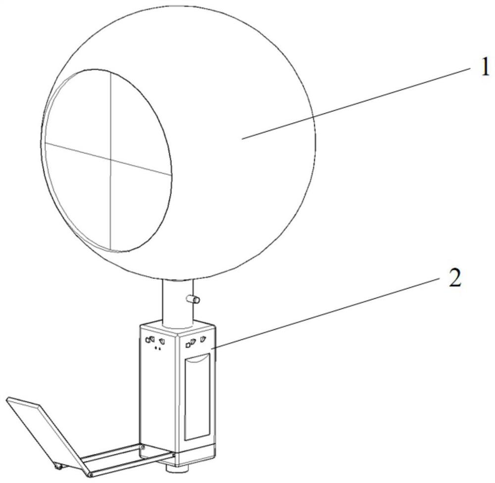
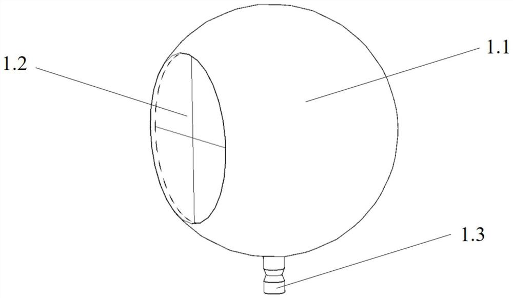
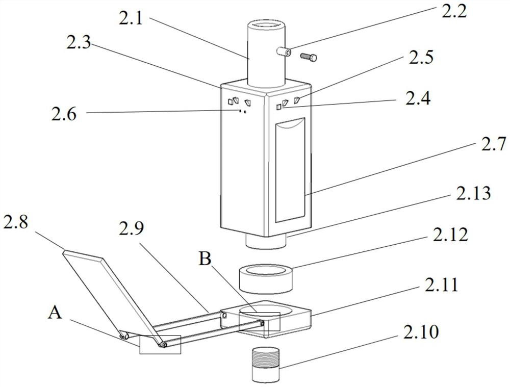
[0053] Assembly of the conversion device: After assembling the conversion target 1 and the base 2 respectively, insert the connecting rod 1.3 of the conversion target 1 into the target connecting column 2.1 of the base 2, and insert the connecting rod 1.3 into the target through the horizontal fixing column 2.2 The position in the connecting column 2.1 is limited and fixed;

[0054] How to use the conversion device: After the conversion device is set on the fixed tripod, the reflective prism 1.2 is aligned with the construction coordinate measuring instrument (usually a total station), and the switch 2.4 on one side of the reflective prism 1.2 is turned on to illuminate the side Lamp 2.5 is turned on, and at the same time, the reflector bracket 2.9 and reflector 2.8 are respectively launched, and the rotating bracket holder 2.11 makes the illumination light of the illuminating lamp 2.5 reflect to the target sphere 1.1, especially the reflecting prism 1.2, through the reflector ...


PUM


Abstract

The invention provides a scanning positioning target. The scanning positioning target comprises a conversion target and a base, the conversion target is used for controlling conversion of coordinates and scanning coordinates and comprises a target sphere, a reflecting prism and a connecting rod, a groove used for installing the reflecting prism is formed in the target sphere, one end of the connecting rod is connected with the target sphere, and the other end of the connecting rod is connected with the base; the base is used for connecting the conversion target with the scanning target supporting frame and comprises a base body and an illuminating lamp, the upper end of the base body is provided with a target connecting column used for being connected with the connecting rod, and the lower end of the base body is provided with a bottom connecting column used for being connected with the scanning target supporting frame; and the illuminating lamp is arranged on the base body and is used for providing light for the conversion target, especially the reflecting prism, so that the influence of a dark light environment on the conversion measurement work of the control coordinates and the scanning coordinates is avoided.

Description

technical field [0001] The invention relates to the technical field of three-dimensional laser scanning, in particular to a scanning positioning target. Background technique [0002] 3D laser scanning technology is developing rapidly. The scanning point cloud data and its derivatives obtained through this technology provide new solutions for engineering projects in many fields. Among them, this technology has a very good application in construction monitoring and measurement. In the construction monitoring measurement, it is necessary to measure the construction control coordinates and scanning control coordinates of the scanning target and substitute them into the coordinate transformation formula to obtain the coordinate transformation matrix, and then convert the scanning coordinates of all scanning point clouds into construction control coordinates. There are many scanning targets for converting scanning coordinates and control coordinates, but such targets cannot be use...

Claims


Application Information

Patent Timeline
Patent Type & Authority Applications(China)
IPC IPC(8): G01B11/24
CPCG01B11/24
Inventor 马增琦杨承昆娄健郭国和王伟力曾思清吴勇生蔡敏文言
Owner HUNAN LIANZHI BRIDGE & TUNNEL TECH
Why Eureka
Try Eureka