High-voltage switch cabinet partial discharge positioning method and system considering temperature field change

A high-voltage switchgear and partial discharge technology, which is applied in radio wave measurement systems, positioning, and electrical measurement, can solve problems such as inaccurate discharge types, missing data from a single sensor, and inaccurate calculation of partial discharge source distances, etc.

Active Publication Date: 2021-06-04
ZAOZHUANG POWER SUPPLY COMPANY OF STATE GRID SHANDONG ELECTRIC POWER +1
View PDF12 Cites 2 Cited by
  • Summary
  • Abstract
  • Description
  • Claims
  • Application Information

AI Technical Summary

Problems solved by technology

[0004] The partial discharge detection methods of high-voltage switchgear include pulse current method, ultrasonic method, transient low voltage method (TEV) and ultra-high frequency method, but the single partial discharge collection method often has problems such as poor positioning accuracy and inaccurate discharge type At the same time, due to different sensitivities, a single sensor may also have abnormal situations such as missing data. Therefore, at present, multi-type sensors are used for simultaneous measurement to improve detection and positioning accuracy.
The inventors found that the prior art did not take into account the influence of the value change of the temperature field in the cabinet on the ultrasonic propagation velocity, and the calculation of the distance of the PD source was inaccurate, resulting in low positioning accuracy of the PD

Method used


Image

  • High-voltage switch cabinet partial discharge positioning method and system considering temperature field change
  • High-voltage switch cabinet partial discharge positioning method and system considering temperature field change
  • High-voltage switch cabinet partial discharge positioning method and system considering temperature field change

Examples


Embodiment 1

[0035] This embodiment provides a method for locating partial discharge in a high-voltage switchgear considering changes in the temperature field;

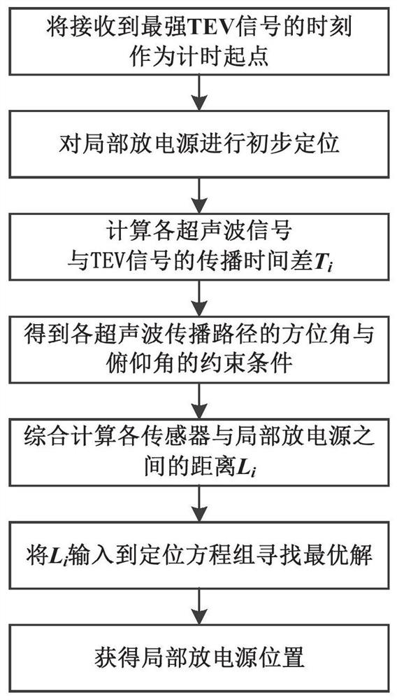
[0036] Such as figure 1 As shown, the partial discharge localization method of high-voltage switchgear considering the change of temperature field includes:

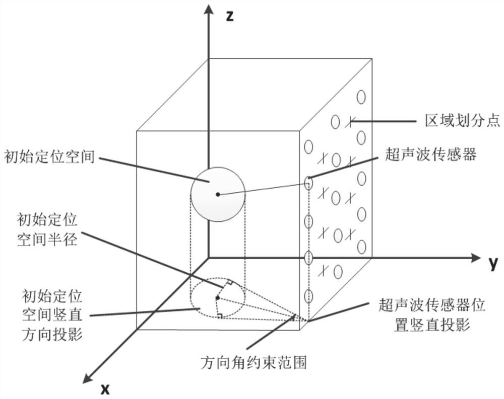
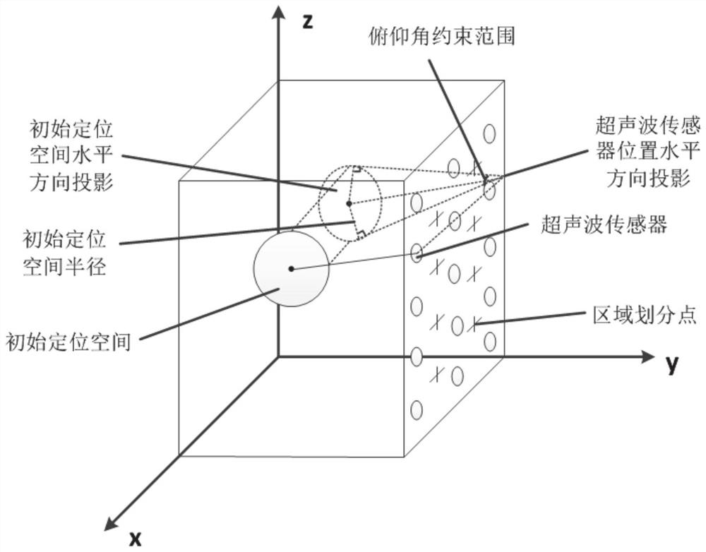
[0037] S101: Preliminarily locate the partial discharge source of the high-voltage switchgear detected by the TEV detector in a spherical space;

[0038] S102: Use m ultrasonic sensors to measure the partial discharge of the high-voltage switchgear, and obtain the propagation time difference T between the initial moment of the abnormal sound wave signal collected by the i-th ultrasonic sensor and the moment when the strongest TEV signal is detected by the TEV detector i ;The value range of i is 1~m;

[0039] S103: According to the spherical space, the propagation time difference T i and the temperature distribution of the ultrasonic propagation path, calculate the predict...

Embodiment 2

[0130] This embodiment provides a high-voltage switchgear partial discharge positioning system that considers changes in the temperature field;

[0131] A high-voltage switchgear partial discharge localization system considering temperature field changes, including:

[0132] The spherical space positioning module is configured to: initially position the partial discharge source of the high-voltage switchgear detected by the TEV detector in a spherical space;

[0133] The propagation time difference acquisition module is configured to: use m ultrasonic sensors to measure the partial discharge of the high-voltage switchgear, and obtain the starting time of the abnormal sound wave signal collected by the i-th ultrasonic sensor and the time between the strongest TEV signal detected by the TEV detector time difference T i ;The value range of i is 1~m;

[0134] The prediction distance calculation module is configured to: according to the spherical space, the propagation time diffe...

Embodiment 3

[0141] This embodiment also provides an electronic device, including: one or more processors, one or more memories, and one or more computer programs; wherein, the processor is connected to the memory, and the one or more computer programs are programmed Stored in the memory, when the electronic device is running, the processor executes one or more computer programs stored in the memory, so that the electronic device executes the method described in Embodiment 1 above.

[0142] It should be understood that in this embodiment, the processor can be a central processing unit CPU, and the processor can also be other general-purpose processors, digital signal processors DSP, application-specific integrated circuits ASiC, off-the-shelf programmable gate arrays FPGA or other programmable logic devices , discrete gate or transistor logic devices, discrete hardware components, etc. A general-purpose processor may be a microprocessor, or the processor may be any conventional processor, ...


PUM


Abstract

The invention discloses a high-voltage switch cabinet partial discharge positioning method and system considering temperature field change. The method comprises the following steps: preliminarily positioning a partial discharge source of a high-voltage switch cabinet detected by a TEV detector in a spherical space; adopting m ultrasonic sensors to carry out partial discharge measurement on the high-voltage switch cabinet, and obtaining the propagation time difference between the starting moment of an abnormal sound wave signal collected by the ith ultrasonic sensor and the moment of the strongest TEV signal detected by the TEV detector; calculating a predicted distance between the ith ultrasonic sensor and the partial discharge source according to the spherical space, the propagation time difference and the temperature distribution condition of the ultrasonic propagation path; calculating the coordinate position of the partial discharge source predicted by the ultrasonic sensor based on the predicted distance between the ultrasonic sensor and the partial discharge source; and based on the coordinate positions, predicted by all the ultrasonic sensors, of the partial discharge source, finding an optimal solution, and obtaining the accurate position of the partial discharge source. The method has the advantage of high positioning precision.

Description

technical field [0001] The present application relates to the technical field of partial discharge location, in particular to a method and system for partial discharge location of a high-voltage switchgear considering temperature field changes. Background technique [0002] The statements in this section merely mention the background art related to this application, and do not necessarily constitute the prior art. [0003] As a complete set of switchgear for receiving and distributing network power and controlling, protecting and monitoring electrical equipment, high-voltage switchgear is widely used in various substations. Compared with the high-voltage power grid, due to the different degrees of problems in the design, manufacture, installation, operation and maintenance of the high-voltage switchgear, the accident rate is relatively high. According to incomplete statistics, in many types of switchgear accidents, the number of switchgear accidents caused by insulation fau...

Claims


Application Information

Patent Timeline
Patent Type & Authority Applications(China)
IPC IPC(8): G01R31/00G01R31/12G01S5/18G06F30/23
CPCG01R31/00G01R31/1209G01S5/18G06F30/23G06F2119/08
Inventor 康文文李森李国亮刘振虎杨凤文韩锋宋士瞻刘玉娇张健王坤代二刚
Owner ZAOZHUANG POWER SUPPLY COMPANY OF STATE GRID SHANDONG ELECTRIC POWER
Why Eureka
Try Eureka