An insulating protective cover installed without power failure

A technology of insulation protection and insulation cavity, applied in the direction of the board/panel/desk of the substation/switchgear, etc., can solve the problems of single-phase grounding or phase-to-phase short circuit, line fault tripping, inability to meet the distribution line, and reduce the number of operations. and the number of people, release the construction force, and shorten the installation time.

Active Publication Date: 2022-07-26
STATE GRID ZHEJIANG ELECTRIC POWER CO LTD JINHUA POWER SUPPLY CO
View PDF0 Cites 0 Cited by
  • Summary
  • Abstract
  • Description
  • Claims
  • Application Information

AI Technical Summary

Problems solved by technology

[0002] The switch on the pole is an important distribution network equipment. The distance between the live and exposed parts of the switch on the pole of the distribution line is relatively close. When small animals such as birds, squirrels, and snakes fall on one or two phases, it will cause single-phase failure of the distribution line. Grounding or phase-to-phase short circuit causes line fault tripping. Faults caused by small animals account for 53% of all distribution line faults every year, causing economic losses and social impacts to power supply companies and users. Installing an insulating protective cover on the lock is time-consuming and inefficient, and cannot meet the concept of high-quality service of power supply companies and the requirements of high power supply reliability

Method used


Image

  • An insulating protective cover installed without power failure
  • An insulating protective cover installed without power failure
  • An insulating protective cover installed without power failure

Examples


Embodiment Construction

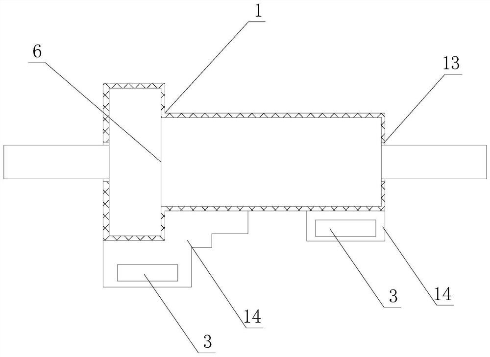
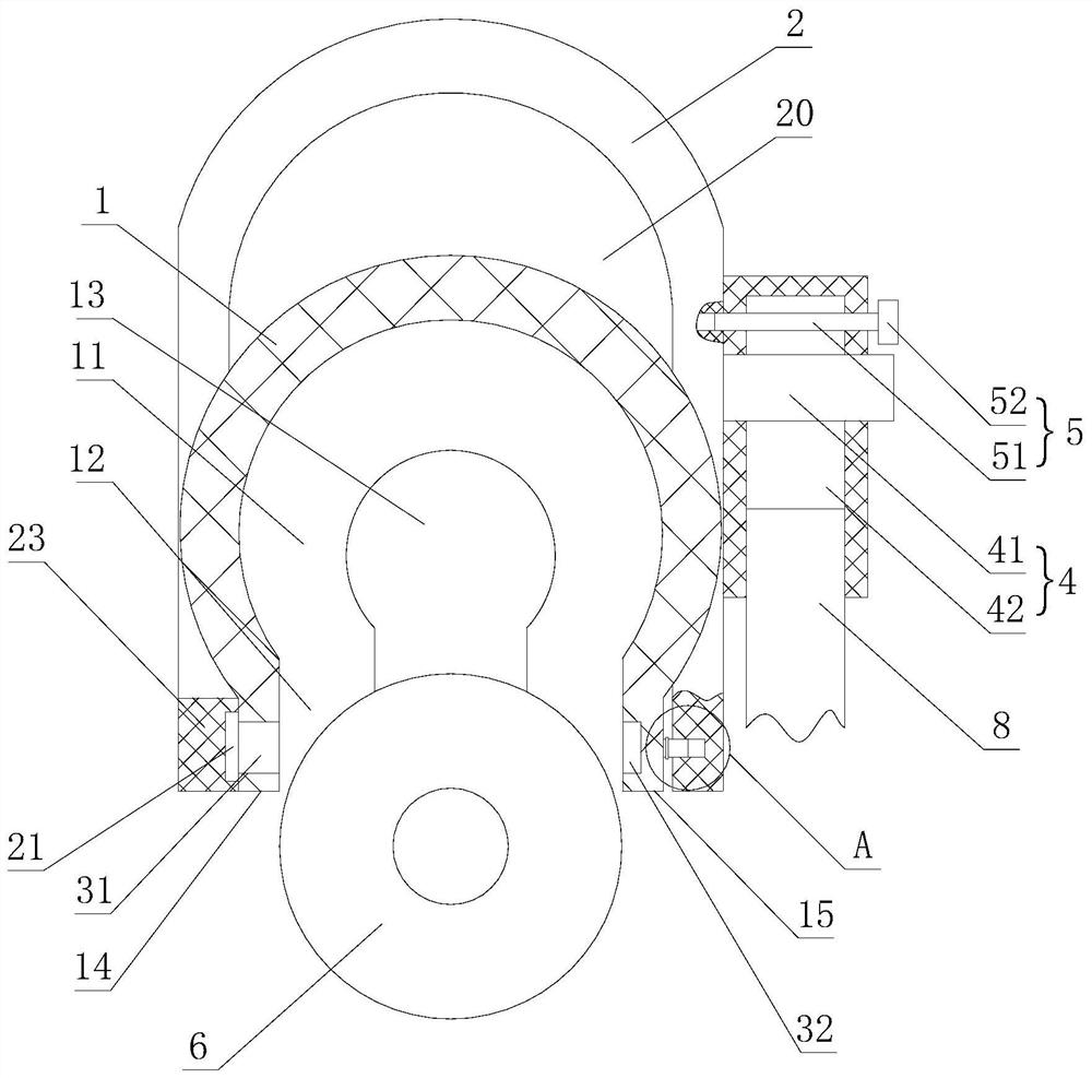
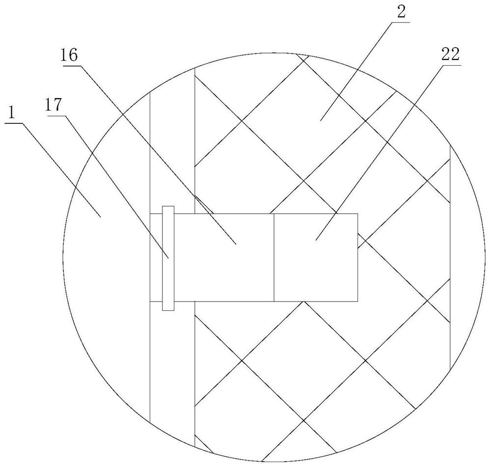
[0022] like figure 1 , figure 2 , image 3 , Figure 4 As shown, an insulating protective cover that is installed without power failure includes a heat-shrinkable silicone rubber body 1 and an insulating actuator 2. The heat-shrinkable silicone rubber body 1 is provided with an insulating cavity 11 that wraps the switch 6 on the column along the length direction. The bottom end of the insulating cavity 11 is provided with an opening 12 , the side walls of both ends of the insulating cavity 11 are provided with mounting holes 13 which are matched with the wires of the switch on the post, and the heat shrinkable silicone rubber body 1 is provided with an opening 12 . There is a magnetic connection structure 3 to prevent the heat-shrinkable silicone rubber body 1 from disengaging. The heat-shrinkable silicone rubber body 1 is detachably mounted on the insulating actuator 2, and the insulating actuator 2 is provided with a connecting rod 8 The rotating body 4 can be rotated 36...


PUM


Abstract

The invention relates to an insulating protective cover installed without interruption, comprising a heat-shrinkable silicone rubber body and an insulating actuator. The heat-shrinkable silicone rubber body is provided with an insulating cavity, the bottom end of the insulating cavity is provided with an opening, and the heat-shrinkable silicone rubber body is further A magnetic connection structure is provided, and the heat-shrinkable silicone rubber body is detachably installed on the insulating actuator; the advantages of the present invention are: the switch on the column is installed in the insulating cavity in the heat-shrinkable silicone rubber body through the opening, and then the heat-shrinkable silicone rubber body is installed in the insulating cavity through the thermal The magnetic connection structure set on the shrinkable silicone rubber body realizes the wrapping and fixing of the heat shrinkable silicone rubber body to the switch on the column. Due to the magnetic function of the magnetic connection structure, the heat shrinkable silicone rubber body does not need manual connection during installation, and it can improve the thermal shrinkage. The fixed quality of the silicone rubber body prevents the effect of disengagement, so that the insulating protective cover can be quickly installed without power failure, which improves the work efficiency, does not require power failure, improves the reliability of the power supply, and reduces the working time.

Description

technical field [0001] The invention relates to an insulating protective cover installed without power failure. Background technique [0002] The switch on the column is an important distribution network equipment. The live exposed parts of the switch on the distribution line are relatively close to each other. When birds, squirrels, snakes and other small animals fall on one or two phases, it will cause a single-phase distribution line. Grounding or phase-to-phase short-circuits cause line faults to trip. The annual faults caused by small animals account for 53% of all distribution line faults, causing economic losses and social impacts to power supply companies and users. The installation of an insulating protective cover on the lock is time-consuming and inefficient, and cannot meet the concept of high-quality service and the requirements of high power supply reliability for power supply companies. SUMMARY OF THE INVENTION [0003] The purpose to be achieved by the pre...

Claims


Application Information

Patent Timeline
Patent Type & Authority Patents(China)
IPC IPC(8): H02B1/06
CPCH02B1/06
Inventor 徐勇俊范晓东方旭光方君王敏郑文献邵建强许谊章建军楼钢朱泽厅周哲权林恺丰吴昊卢鸣凯邵大威蒋晓林何昕沈然杨昶宇
Owner STATE GRID ZHEJIANG ELECTRIC POWER CO LTD JINHUA POWER SUPPLY CO
Why Eureka
Try Eureka