Transmission method and device, reception method and device of control channel

A control channel and channel technology, applied in the field of communication, can solve the problem of low transmission efficiency of control channel

Active Publication Date: 2022-05-13
ZTE CORP
View PDF4 Cites 0 Cited by
  • Summary
  • Abstract
  • Description
  • Claims
  • Application Information

AI Technical Summary

Problems solved by technology

[0007] Embodiments of the present invention provide a method and device for sending a control channel, and a method and device for receiving it, so as to at least solve the technical problem in the related art that the transmission efficiency of the control channel is low due to the blind detection of the control channel by the terminal

Method used


Image

  • Transmission method and device, reception method and device of control channel
  • Transmission method and device, reception method and device of control channel
  • Transmission method and device, reception method and device of control channel

Examples


Embodiment 1

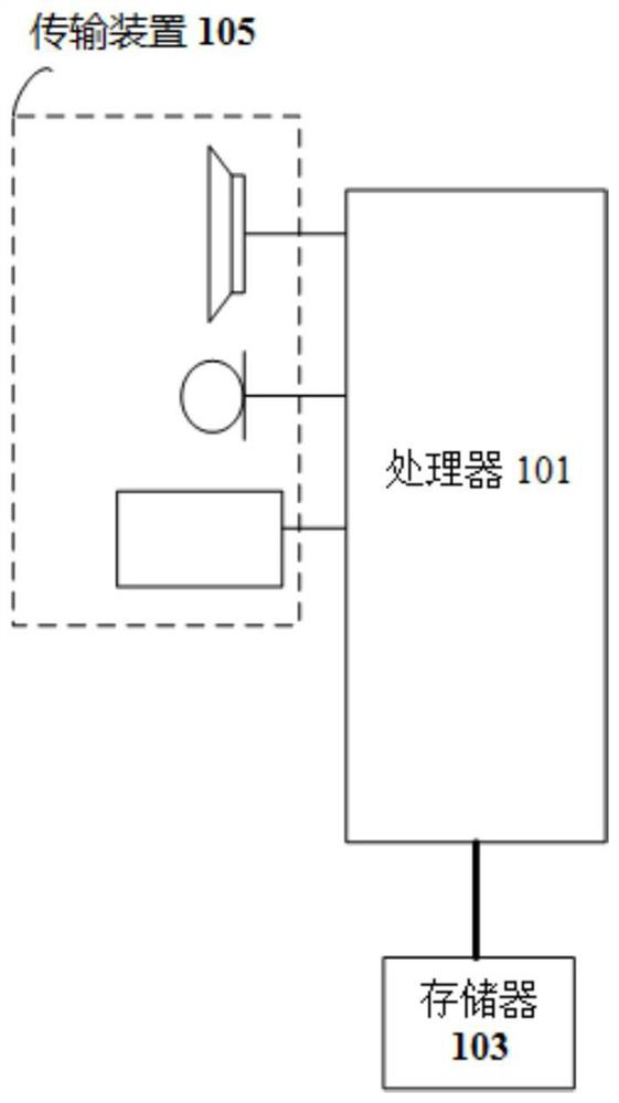
[0081] The method embodiment provided in Embodiment 1 of the present application may be executed in a mobile terminal, a computer terminal, or a similar computing device. Take running on a computer terminal as an example, such as figure 1As shown, the computer terminal may include one or more (only one is shown in the figure) processors 101 (the processors 101 may include but not limited to processing devices such as microprocessor MCU or programmable logic device FPGA, etc.), for storing Data storage 103, and transmission means 105 for communication functions. Those of ordinary skill in the art can understand that, figure 1 The shown structure is only for illustration, and it does not limit the structure of the above-mentioned electronic device.

[0082] The memory 103 can be used to store software programs and modules of application software, such as program instructions / modules corresponding to the control method of the device in the embodiment of the present invention, a...

Embodiment approach 1

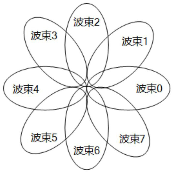
[0113] Each transmit beam is respectively bound to a control channel time-frequency resource.

[0114] like image 3 and Figure 4 (including Figure 4a , Figure 4b as well as Figure 4c ), assuming that the base station has a total of 8 transmit beams (respectively beam 0 to beam 7) that can be used to transmit control channels, and the number or beam identity (Beam identity, referred to as Beam ID or beam ID) of the i-th transmit beam is i , where i is an integer less than 8.

[0115] The base station reserves N time-frequency resources for downlink control channel transmission, where the value of N is equal to the number of transmit beams that can be used to transmit downlink control channels, that is, N=8, 8 transmit beams and 8 downlink control channel time-frequency resources There is a one-to-one correspondence between them. The corresponding relationship is predefined (that is, pre-agreed by the base station and the terminal), or notified to the terminal by the ba...

Embodiment approach 2

[0124] Multiple transmit beams are bound to a common control channel time-frequency resource.

[0125] Figure 5 (including Figure 5a , Figure 5b as well as Figure 5c ), assuming that the base station has a total of M transmit beams that can be used to transmit the downlink control channel, where the i-th transmit beam change or beam identity (beam ID, referred to as Beam ID or beam ID) is i, and i is an integer less than M .

[0126] The base station reserves N downlink control channel resources for downlink control channel transmission, where the value of N is smaller than the number of transmission beams that can be used to transmit the downlink control channel, that is, N Figure 5a , Figure 5b , Figure 5c Schematic diagrams of the corresponding relationship between the transmission beams (Beam0 to Beam15) of the base station and the transmission resources (resource 0 to resource 3) of the downlink control channel in the case of M=16 and N=4 are given respectively. ...


PUM


Abstract

The present invention provides a control channel sending method and device, receiving method and device. Wherein, the sending method includes: the first device acquires the resource information of the first type of sending resource of the control channel; the first device determines the second type of sending resource of the control channel according to the resource information of the first type of sending resource, wherein, the second type The transmission resource is a transmission resource different from the first type of transmission resource; the first device sends a control channel to the second device on the first type of transmission resource and the second type of transmission resource. The invention solves the technical problem of low transmission efficiency of the control channel caused by blind detection of the control channel by the terminal in the related art.

Description

[0001] This application is a divisional application of the Chinese patent application with the application number "201610575838.2", the application date is "July 20, 2016", and the title is "control channel transmission method and device, receiving method and device". technical field [0002] The present invention relates to the communication field, in particular, to a control channel sending method and device, and a receiving method and device. Background technique [0003] Traditional cellular network systems mainly use low-frequency bands (such as 300MHz to 3GHz) spectrum. However, with the increasing demand for communication services, traditional low-frequency bands are becoming more and more crowded, which is no longer sufficient to meet future communication needs. Therefore, using high-frequency spectrum resources for mobile broadband communications has become a trend in future network development. [0004] High-frequency communication is characterized by relatively se...

Claims


Application Information

Patent Timeline
Patent Type & Authority Patents(China)
IPC IPC(8): H04L27/26H04L5/00H04B7/06H04W72/04
CPCH04L27/2613H04L5/0048H04L5/0053H04L5/0094H04B7/0617H04W72/0446H04L5/0051H04W72/046H04L5/0016H04W72/20H04W72/23H04L1/00
Inventor 弓宇宏鲁照华张淑娟毕峰
Owner ZTE CORP
Why Eureka
Try Eureka