Panoramic multifunctional camera

A camera and multi-functional technology, applied in the field of cameras, can solve the problems of adjustment effect and poor operation convenience in the camera process, and achieve the effects of large camera or monitoring range, good collection field of view, and improved clarity

Active Publication Date: 2021-06-04
中研电子(杭州)有限公司
View PDF7 Cites 0 Cited by
  • Summary
  • Abstract
  • Description
  • Claims
  • Application Information

AI Technical Summary

Problems solved by technology

[0003] Although the current camera can be used for video recording or real-time image monitoring, it cannot fully adjust the angle according to the needs of the camera during use, resulting in poor operation convenience during the camera process. For this reason, a panoramic view is now provided Multifunctional camera to solve the above technical problems

Method used


Image

  • Panoramic multifunctional camera
  • Panoramic multifunctional camera
  • Panoramic multifunctional camera

Examples


Embodiment 1

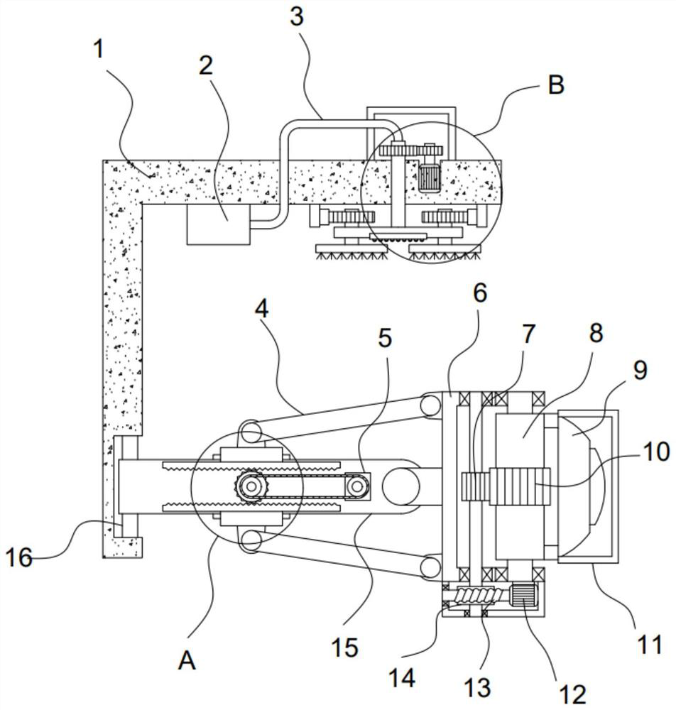
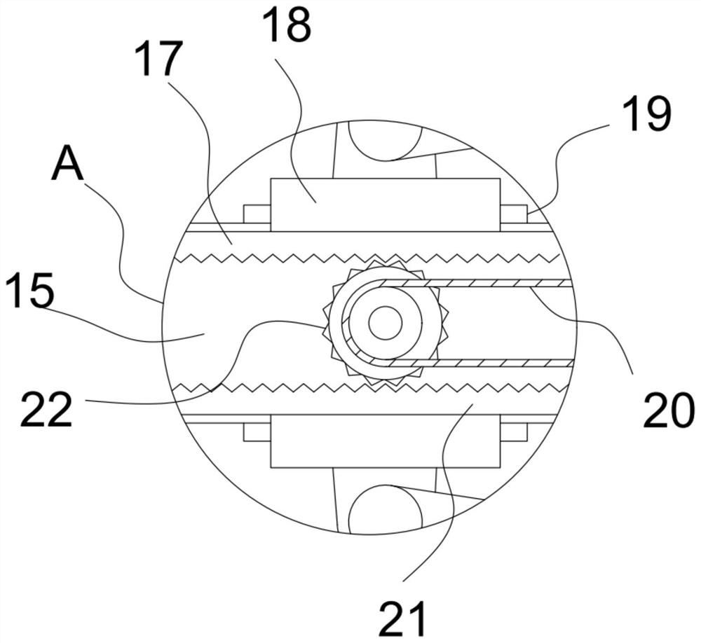
[0025] See Figure 1-5 A panoramic multi-function camera, including the mounting frame 1, the camera 9, and a glass protective cover 11 on the camera 9, and the mounting frame 1 is provided with a deflection plate 15, and the deflection plate 15 is hinged to carry the camera 9. The carrier 6 is provided with a front and rear rotating mechanism for driving the camera 9 relative to the carrier 6, and the deflection plate 15 is rotated on the mounting frame 1, and the deflection plate 15 is fixed to the deflection plate 15. The motor I5 is provided with an upper and lower rotating mechanism driven by the motor I5, the mounting frame 1, and the motor III 26 driven by the mounting frame 1, and the motor III 26 drives a deflection mechanism for driving the deflection plate 15. The mounting frame 1 is provided with a cleaning mechanism for cleaning the glass protective cover 11.

[0026] The camera 9 of the device is mounted on the carrier 6, and the arranged mounting frame 1 is provided ...

Embodiment 2

[0032] On the basis of Example 1, the apparatus also provided a deflection mechanism including a threaded rod 25 driven by the motor III 26, and the threaded rod 25 is threaded with a threaded sleeve 24, and the mounting frame 1 is vertical. The column 16 is fixed, and the biasing plate 15 is rotated on the column 16, and the threaded sleeve 24 is hinged between the biasing plate 15.

[0033] The set motor III 26 can drive the threaded rod 25 rotation, the threaded lever 25 drives the threaded junction 24 sliding, the threaded sleeve 24 drives the deflection plate 15 to achieve a deflection around the column 16, and realizes the carrier 6 to carry the camera. 9 Perform a relative column 16's deflection effect, enabling the enlargement and adjustment of the camera 9 captured or monitoring.

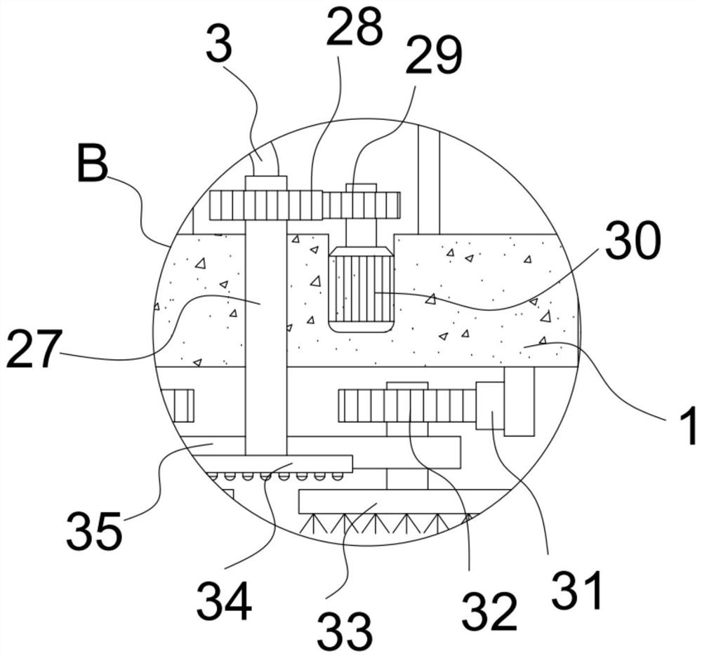
[0034] The cleaning mechanism of the device includes a hollow shaft 27 that is rotatably mounted on the mounting frame 1, and the hollow shaft 27 is sleeved, and the rotating plate 35 is fixed,...


PUM


Abstract

The invention discloses a panoramic multifunctional camera, and relates to the technical field of cameras. The panoramic multifunctional camera comprises a mounting rack, a camera and a glass protection cover covering the camera; a motor I fixed on a deflection plate is fixed on the deflection plate, and a motor III is in driving connection with a deflection mechanism used for driving the deflection plate to deflect; the camera is supported through the arranged bearing frame, the front-back rotating mechanism can turn the camera in the front-back direction, and the arranged up-down rotating mechanism can turn the camera in the up-down direction, so that the monitoring or shooting range of the camera can be flexibly adjusted according to actual use requirements; the deflection mechanism can drive the deflection plate to deflect, so that the position of the camera on the bearing frame is further adjusted, and a larger camera shooting or monitoring range is achieved; the arranged sweeping mechanism can fully sweep and clean a glass protection cover of the camera when the glass protection cover rotates to be vertically upward, so that the camera is ensured to have a good and transparent acquisition view field.

Description

Technical field [0001] The present invention relates to the field of camera, in particular a panoramic multi-function camera. Background technique [0002] The camera is also known as computer camera, computer eye, electronic eye, etc., is a video input device, which is widely used in video conferencing, telemedicine and real-time monitoring. Ordinary people can also have images with images in the network with each other, with sound talks and communication. In addition, people can also use them for currently various popular digital images, audio and video processing, and the like. [0003] The current camera can be used for video recording or real-time image monitoring, but in the process of use, the full adjustment effect of the image cannot be performed according to the needs of the imaging, resulting in a poor operation of the camera process, for this, now provides a panoramic Multi-function camera to solve the above technical problems. Inventive content [0004] It is an obj...

Claims


Application Information

Patent Timeline
Patent Type & Authority Applications(China)
IPC IPC(8): H04N5/225H04N5/232F16M11/06
CPCF16M11/06H04N23/957H04N23/52H04N23/51H04N23/695Y02E10/50
Inventor 顾华领秦建利杨浈洁平永仓许国伟平忠奇
Owner 中研电子(杭州)有限公司
Why Eureka
Try Eureka