Red date pitting device using barrel-shaped sawtooth opening for food processing

A food processing and pitting device technology, which is applied in fruit pitting devices, applications, food science, etc., can solve the problems of low efficiency of pitting, easy deformation of red dates, and low efficiency of pulp protection

Active Publication Date: 2021-06-08
魏明
View PDF7 Cites 0 Cited by
  • Summary
  • Abstract
  • Description
  • Claims
  • Application Information

AI Technical Summary

Problems solved by technology

[0004]In order to overcome the single processing, the efficiency is not high, the strength of the machine is relatively large, the whole jujube is prone to deformation, and more jujube pulp is taken out when the pit is removed, which is harmful to the pulp. The protection efficie

Method used


Image

  • Red date pitting device using barrel-shaped sawtooth opening for food processing
  • Red date pitting device using barrel-shaped sawtooth opening for food processing
  • Red date pitting device using barrel-shaped sawtooth opening for food processing

Examples


Embodiment 1

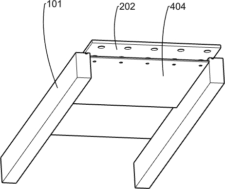
[0070] A kind of jujube pitting device for food processing using barrel-shaped sawtooth mouth, such as Figure 1-2 Shown in and 4-5, include vehicle frame 1, guide rail 101, connecting plate 1011, support plate 102, support frame 103, the first fixed plate 104, collecting frame 6 and denucleating mechanism, vehicle frame 1 is made of a flat plate and four Two guide rails 101 are fixedly installed on the front and rear sides of the upper part of the flat plate of the vehicle frame 1 near the left side, the front and rear sides of the connecting plate 1011 are fixedly connected to the inner side of the two guide rails 101 near the left end, and the two support plates 102 are respectively Fixedly installed on the right side of the upper part of the two guide rails 101, the front and rear ends of the support frame 103 are respectively fixedly installed on the top of the two guide rails 101 near the middle position, and the first fixed plate 104 is fixedly installed on the upper sid...

Embodiment 2

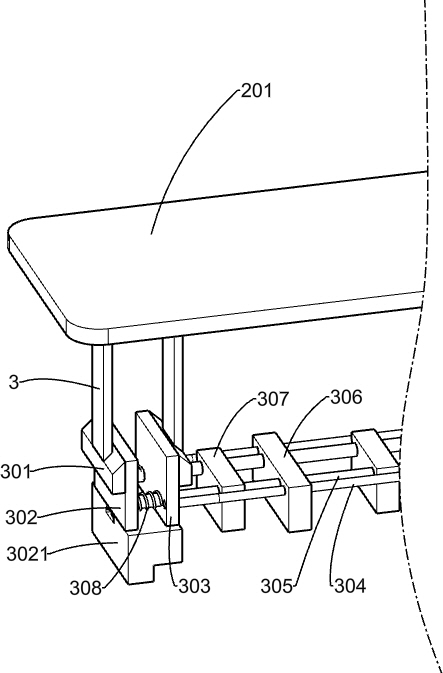
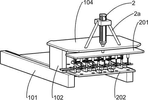
[0073] On the basis of Example 1, such as figure 2 and 4 As shown in -5, the denucleating mechanism includes a support 2a, a first cylinder 2, a second fixed plate 201, a material receiving plate 202, a first pole 203, a slide bar 204, a first spring 205, a sliding sleeve 206, and a sliding frame 207. Sawtooth tube 208 and clamping mechanism, the bracket 2a is fixedly installed in the upper right middle position of the first fixed plate 104, the first cylinder 2 is fixedly installed on the bracket 2a, and the telescopic rod of the first cylinder 2 passes through the first fixed plate 104, the second fixed plate 201 is fixedly installed on the lower end of the telescopic rod of the first cylinder 2, the front and rear sides of the material receiving plate 202 are slidingly connected with the inner sides of the two guide rails 101, there are five first support rods 203, five second A rod 203 is arranged and fixedly installed on the lower left side of the second fixed plate 201...

Embodiment 3

[0078] On the basis of Example 2, such as image 3 and 6 As shown, a pusher mechanism is also included, and the pusher mechanism includes a fixed cylinder 4, a sliding column 401, a push plate 403, a third spring 402 and a baffle plate 404, and five fixed cylinders 4 are evenly distributed in an array on the second fixed plate On the right side of the lower part of 201, five sliding columns 401 are slidingly connected with the lower sides of five fixed cylinders 4 respectively, each push plate 403 is fixedly installed on the lower end of each sliding column 401, and five third springs 402 are sleeved on the sliding On the column 401 , the third spring 402 is located between the fixed cylinder 4 and the push plate 403 , the baffle plate 404 is fixedly installed between the two guide rails 101 , and the guide plate is located in the middle below the material receiving plate 202 .

[0079] When the part of red dates with the pitting of the stock plate 202 is pushed to the top of...


PUM


Abstract

The invention relates to a pitting device, in particular to a red date pitting device using a barrel-shaped sawtooth opening for food processing. The invention aims to provide the red date pitting device using the barrel-shaped sawtooth opening for food processing, which can prevent red dates from deforming, has a pre-clamping function and is higher in pitting efficiency. According to the technical scheme, the red date pitting device using the barrel-shaped sawtooth opening for food processing comprises a frame, guide rails, a connecting plate, supporting plates and the like; the frame consists of a flat plate and four wheels; the two guide rails are fixedly installed on the front side and the rear side of the left portion of the upper portion of the flat plate of the frame; the front side and the rear side of the connecting plate are fixedly connected with the positions, close to the left ends, of the inner sides of the two guide rails; and the two supporting plates are fixedly installed at the right sides of the upper portions of the two guide rails correspondingly. According to the red date pitting device, the pitting process is conducted through a pipe with the sawtooth opening; when stress is small, sawteeth can be easily inserted into red dates, and meanwhile, date pits and date flesh can be conveniently separated, so that the pitting efficiency is improved.

Description

technical field [0001] The invention relates to a pitting device, in particular to a jujube pitting device for food processing using a barrel-shaped sawtooth mouth. Background technique [0002] Red jujubes are used for edible preserved fruit after pitting, processing, etc., but the existing pitting is generally manual operation. After the operator fixes the red dates with one hand, the other hand inserts from the top of the red dates through a harder tubular object, and directly pushes the red dates. The jujube pits are produced by hand. The process of manually removing the jujube pits is a single process, and the efficiency is not high. Some factories use machines to remove the pits. However, due to the strong force of the machine, the entire red dates are prone to deformation, and the jujubes that are taken out during pitting There is more meat, and the protection efficiency of the pulp is low, and due to the greater impact force, it is easy for the whole jujube to be pus...

Claims


Application Information

Patent Timeline
IPC IPC(8): A23N4/08
CPCA23N4/08
Inventor 魏明
Owner 魏明
Why Eureka
Try Eureka