Rotor wing of rotorcraft and rotorcraft

A rotorcraft and rotor technology, applied in the field of aircraft, can solve the problems of low aerodynamic efficiency of rotor drones, less research on rotors, and low lift coefficient, and achieve the effects of improving aerodynamic efficiency, improving aerodynamic efficiency, and high lift-to-drag ratio

Active Publication Date: 2021-06-08
BEIJING AIRLANGO TECH CO LTD
View PDF3 Cites 0 Cited by
  • Summary
  • Abstract
  • Description
  • Claims
  • Application Information

AI Technical Summary

Problems solved by technology

At present, there are few researches on rotors such as logistics distribution, plant protection, and aerial photography, which are mostly under low Reynolds number (below 500,000) flows.
Existing rotors generally have problems such as low lift coefficient and low lift-to-drag ratio under low Reynolds number flow, which makes the aerodynamic efficiency of rotor UAVs low

Method used


Image

  • Rotor wing of rotorcraft and rotorcraft
  • Rotor wing of rotorcraft and rotorcraft
  • Rotor wing of rotorcraft and rotorcraft

Examples


Embodiment Construction

[0030] Specific embodiments of the present disclosure will be described in detail below in conjunction with the accompanying drawings. It should be understood that the specific embodiments described here are only used to illustrate and explain the present disclosure, and are not intended to limit the present disclosure.

[0031] The orientation terms such as up and down in this embodiment refer to the conventional operating attitude of the rotor and the rotorcraft after the rotor is installed on the aircraft, and should not be regarded as limiting.

[0032] The rotor of the rotorcraft of the present disclosure and the rotorcraft will be described in detail below with reference to the accompanying drawings. If there is no conflict, the features in the following embodiments and implementations can be combined with each other.

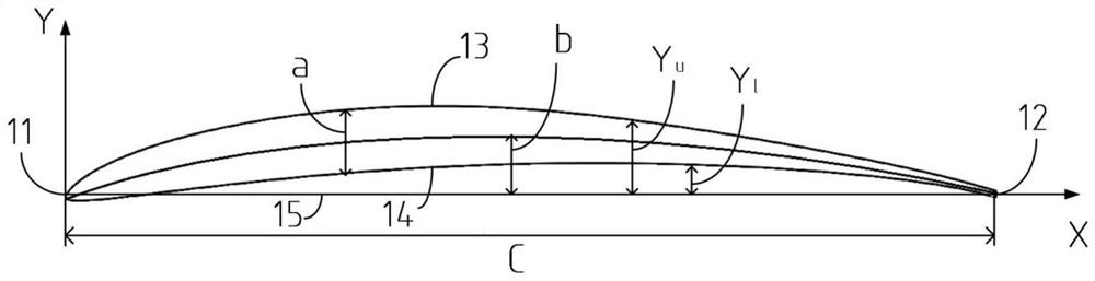
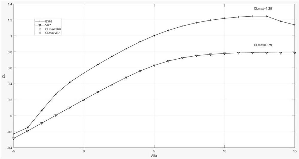
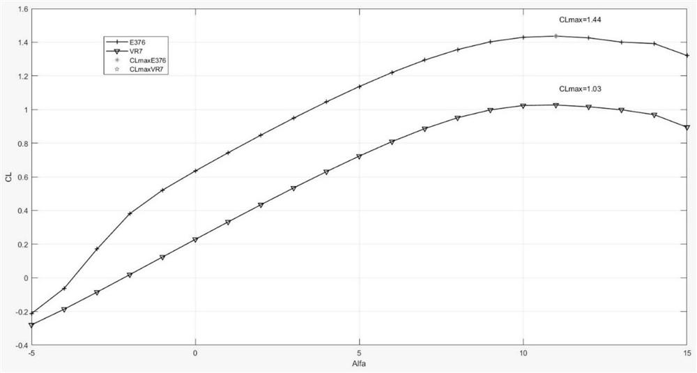
[0033] Such as Figure 12 and Figure 13 As shown, the present disclosure provides a rotor of a rotorcraft. The rotor includes a blade 1 and a hub, an...


PUM


Abstract

The invention discloses a rotor wing of a rotorcraft and the rotorcraft. The rotor wing of the rotorcraft comprises blades and a propeller hub, the blades are installed on a driving assembly of the rotorcraft through the propeller hub, the wing section of each blade is composed of a front edge, a tail edge, an upper arc line and a lower arc line, and the upper arc line and the lower arc line are located between the front edge and the tail edge. The ratio a / c of the maximum thickness a of the airfoil of each blade to the chord length c of the airfoil is 6.85%, and the maximum thickness is located at the position where x / c is 30.5%; and the ratio b / c of the maximum camber b of the airfoil of each blade to the chord length c of the airfoil is 6.6%, and the maximum camber b is located at the position where x / c is 47.1%. The rotor wing obtained through the technical scheme has higher aerodynamic efficiency and lighter weight, and under the same lifting surface distribution design, the required rotating speed is lower, and a noise is lower.

Description

technical field [0001] The present disclosure relates to the technical field of aircraft, and in particular, relates to a rotor of a rotorcraft and the rotorcraft. Background technique [0002] Improving aerodynamic efficiency is an important task in aircraft design. For rotorcraft, it is necessary to reduce the consumed power as much as possible while producing the same lift, or to generate as much lift as possible while consuming the same power. capabilities are important. [0003] The airfoil of a rotorcraft plays an important role in improving aerodynamic efficiency. Existing rotors are mainly designed around large manned aircraft, which are usually in the flow of high Reynolds number (generally above 1,000,000). At present, there are few researches on rotors such as logistics distribution, plant protection, aerial photography, etc., which are mostly under low Reynolds number (below 500,000) flows. Existing rotors generally have problems such as low lift coefficient ...

Claims


Application Information

Patent Timeline
Patent Type & Authority Applications(China)
IPC IPC(8): B64C27/32B64C27/467B64C27/473
CPCB64C27/32B64C27/467B64C27/473B64C3/10
Inventor 周东岳姜欣宏马聪卢鹏李振凯孙恒盛闫波郜奥林刘金来唐河森
Owner BEIJING AIRLANGO TECH CO LTD
Why Eureka
Try Eureka