
Rotorcraft, rotorcraft blades and their airfoils

A technology for rotorcraft and blades, applied in the field of aircraft, can solve the problems of low Reynolds number, low aerodynamic efficiency, low lift coefficient and lift-to-drag ratio, etc., and achieve the effects of improving aerodynamic efficiency, improving aerodynamic efficiency, and increasing lift-drag ratio.

Active Publication Date: 2021-08-27
BEIJING SANKUAI ONLINE TECH CO LTD
View PDF17 Cites 0 Cited by
  • Summary
  • Abstract
  • Description
  • Claims
  • Application Information

AI Technical Summary

Problems solved by technology

The existing airfoils are mainly designed for large-scale manned aircraft, and the Reynolds number is generally above 1,000,000, while the multi-rotor drones on the market are small in size and low in Reynolds number, generally below 1,000,000. At present, there are few airfoils that can provide excellent aerodynamic efficiency. The airfoils in related technologies generally have low lift coefficient and lift-to-drag ratio at low Reynolds numbers, resulting in low aerodynamic efficiency.

Method used


Image

  • Rotorcraft, rotorcraft blades and their airfoils
  • Rotorcraft, rotorcraft blades and their airfoils
  • Rotorcraft, rotorcraft blades and their airfoils

Examples


Embodiment Construction

[0032] Specific embodiments of the present disclosure will be described in detail below in conjunction with the accompanying drawings. It should be understood that the specific embodiments described here are only used to illustrate and explain the present disclosure, and are not intended to limit the present disclosure. The orientation terms such as up and down in this embodiment refer to the conventional operating attitude of the rotor and the rotorcraft after the rotor is installed on the aircraft, and should not be regarded as limiting.

[0033] The airfoil used for the rotorcraft blade of the present disclosure will be described in detail below with reference to the accompanying drawings. In the case of no conflict, the features in the following embodiments and implementations can be combined with each other.

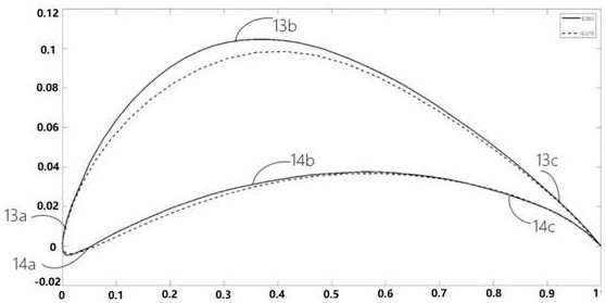
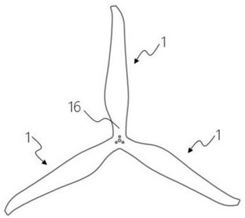
[0034] Such as figure 1 and figure 2 As shown, the present disclosure provides an airfoil for a rotorcraft blade consisting of a leading edge 11, a trailing edg...


PUM


Abstract

The present disclosure relates to a rotorcraft, a blade of the rotorcraft, and an airfoil thereof, wherein the airfoil is composed of a leading edge, a trailing edge, and upper and lower arcs between the leading and trailing edges, and the wing The ratio of the maximum thickness of the airfoil to the chord length of the airfoil is, the maximum thickness is at; The trailing edge distances, , and values ​​have a maximum error of ±3%, respectively. Through the above technical solutions, a higher lift-to-drag ratio can be provided for the rotorcraft at a low Reynolds number, thereby improving the aerodynamic efficiency of the rotorcraft. In addition, due to the improved aerodynamic efficiency of the rotorcraft, under the condition of the same lift surface distribution, the required rotational speed is lower, making it possible to reduce the noise generated during the flight of the rotorcraft.

Description

technical field [0001] The present disclosure relates to the technical field of aircraft, and in particular, to a rotorcraft, a blade of the rotorcraft and an airfoil thereof. Background technique [0002] Improving aerodynamic efficiency is an important task in aircraft design. For rotorcraft, it is necessary to reduce the consumed power as much as possible while producing the same lift, or to generate as much lift as possible while consuming the same power. capabilities are important. [0003] The airfoil is the two-dimensional cross-section perpendicular to the leading edge of the rotor at any position in the span. It is the source of the pressure difference between the upper and lower surfaces of the rotor. It has an important impact on the lift or thrust of the rotor, the level of aerodynamic noise, and even the performance of the aircraft. The existing airfoils are mainly designed for large-scale manned aircraft, and the Reynolds number is generally above 1,000,000, ...

Claims


Application Information

Patent Timeline
Patent Type & Authority Patents(China)
IPC IPC(8): B64C27/473B64C27/32
CPCB64C27/32B64C27/473
Inventor 毛一年周东岳姜欣宏初征郜奥林杨芳刘金来马聪赵龙智刘璐
Owner BEIJING SANKUAI ONLINE TECH CO LTD
Learn More