
Electric connector and its locking device

A technology of electrical connectors and locking devices, applied in the field of electrical connectors, can solve problems such as unfavorable design of electronic products, complex structure of electrical connectors, etc., and achieve the effect of increasing self-locking function

Inactive Publication Date: 2003-11-26
FOXCONN (KUNSHAN) COMPUTER CONNECTOR CO LTD +1
View PDF2 Cites 0 Cited by
  • Summary
  • Abstract
  • Description
  • Claims
  • Application Information

AI Technical Summary

Problems solved by technology

All these inconveniences also make the structure of the entire electrical connector complex, which is not conducive to the lightweight design of the electronic product

Method used


Image

  • Electric connector and its locking device
  • Electric connector and its locking device
  • Electric connector and its locking device

Examples


Embodiment Construction

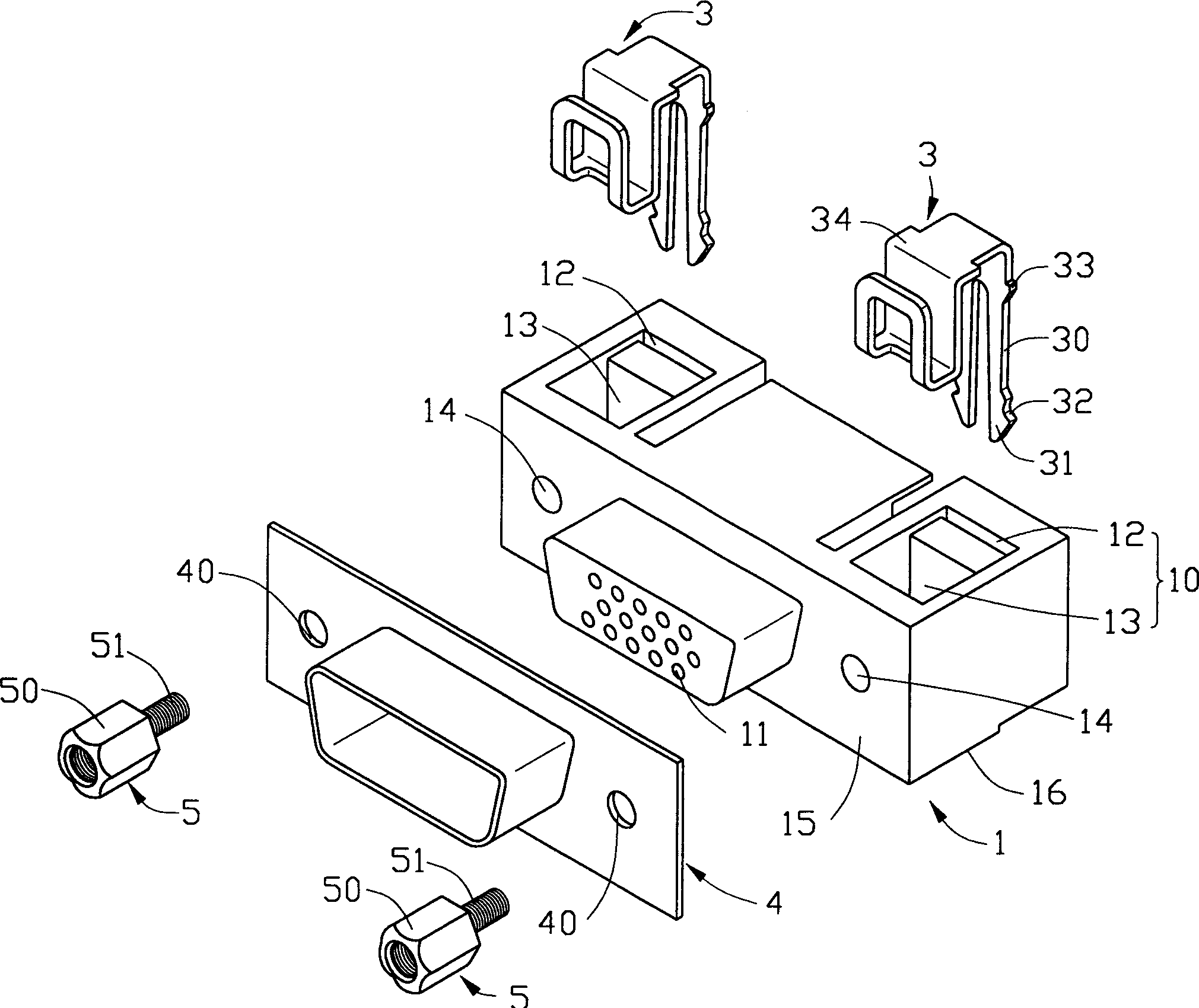
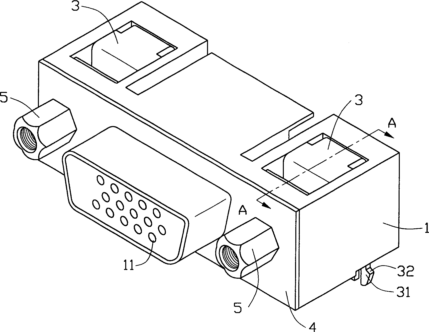
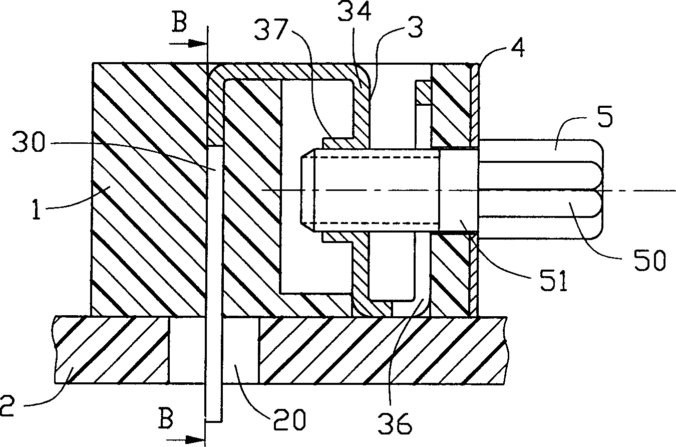
[0011] see figure 1 and figure 2 As shown, the electrical connector of the present invention includes an elongated insulating body 1, and a plurality of terminal receiving grooves 11 are opened at appropriate positions in the insulating body 1 from the front surface to the rear, and a plurality of metal conductive terminals (not shown) are accommodated in the corresponding plurality of terminal receiving grooves. Inside 11, the end of the insulating body 1 is provided with a set of joint spaces 10 downward from the top surface. In this embodiment, the joint space 10 is composed of an alcove 13 and a channel 12 penetrating through the connecting surface 16 of the insulating body 1, and there is a through The through hole 14 of the mating surface 15 of the insulating body 1 communicates with the alcove 13 of the assembly space. The locking device 3 of the electrical connector of the present invention is accommodated in the assembly space 10 .

[0012] see Figure 5 As shown,...


PUM


Abstract

The present invention relates to an electric connector. It is equipped with a locking device consisting of existent fastening member (fastening pin) and screw-retaining member, and its utilizes a special structure to implement self-locking function. Said locking device includes fastening member and retaining member, in which the fastening member includes fixing portion and fastening pin, said fixing portion is received in the described assembly connected space of the insulating self-body, and is a multibent structure, on which the assembly-connecting hole is opened, and the fastening pin is extended from one end of fixing portion so as to fix the electric connector to printed circuit. Said retaining member possesses the assembly-connecting portion matched with assembly-connecting hole of fixing portion so as to make the fastening member obtain self locking function.

Description

【Technical field】 [0001] The invention relates to an electrical connector, in particular to an electrical connector with a locking device for positioning the electrical connector on a printed circuit board. 【Background technique】 [0002] The existing electrical connectors related to this case are usually provided with a buckle member for positioning the electrical connector on the printed circuit board and a threaded locking member with an assembly hole for matching with the screw member. For related prior art, please refer to US Patent Nos. 5,709,556 and 4,874,336, and Taiwan Patent Application Nos. 81,212,364 and 83,200,254, etc. These existing fastening components and locking components are arranged separately, requiring a large number of parts to complete the functions, resulting in relatively many manufacturing and assembly processes, which is not conducive to reducing production costs and simplifying processes. In addition, since the locking member itself has no elas...

Claims


Application Information

Patent Timeline
Patent Type & Authority Patents(China)
IPC IPC(8): H01R13/73H01R13/74
Inventor 朱自强张国发胡伦松顾浩
Owner FOXCONN (KUNSHAN) COMPUTER CONNECTOR CO LTD
Learn More