
FPGA-based chaotic radar emission signal real-time generation system and method

A technology of chaotic signals and transmitting signals, applied in radio wave measurement systems, instruments, etc., can solve problems such as unpredictability, aperiodic chaotic signals, and huge signal differences, and achieve easy transplantation, reduced data collection, and high portability Effect

Active Publication Date: 2021-06-08
NAT SPACE SCI CENT CAS
View PDF19 Cites 3 Cited by
  • Summary
  • Abstract
  • Description
  • Claims
  • Application Information

AI Technical Summary

Problems solved by technology

The chaotic signal is very sensitive to the initial value, and a slight change in the initial value will cause a huge difference in the subsequent signal; and the chaotic signal has the characteristics of aperiodic and unpredictable

Method used


Image

  • FPGA-based chaotic radar emission signal real-time generation system and method
  • FPGA-based chaotic radar emission signal real-time generation system and method
  • FPGA-based chaotic radar emission signal real-time generation system and method

Examples


Embodiment 1

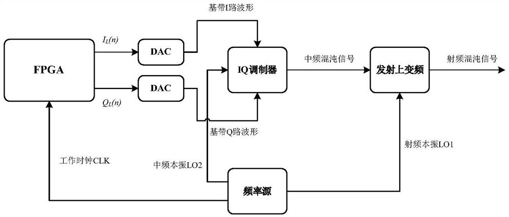
[0052] Embodiment 1 of the present invention proposes a real-time generation system of a chaotic radar transmission signal based on FPGA, said system comprising: a baseband IQ path waveform generation module, a DAC module, an IQ modulator, an emission up-conversion module and a frequency source; wherein,

[0053] The baseband IQ channel waveform generation module is realized by FPGA, which is used to generate the baseband I channel waveform data and the baseband Q channel waveform data of the chaotic radar respectively, and input them into the DAC module;

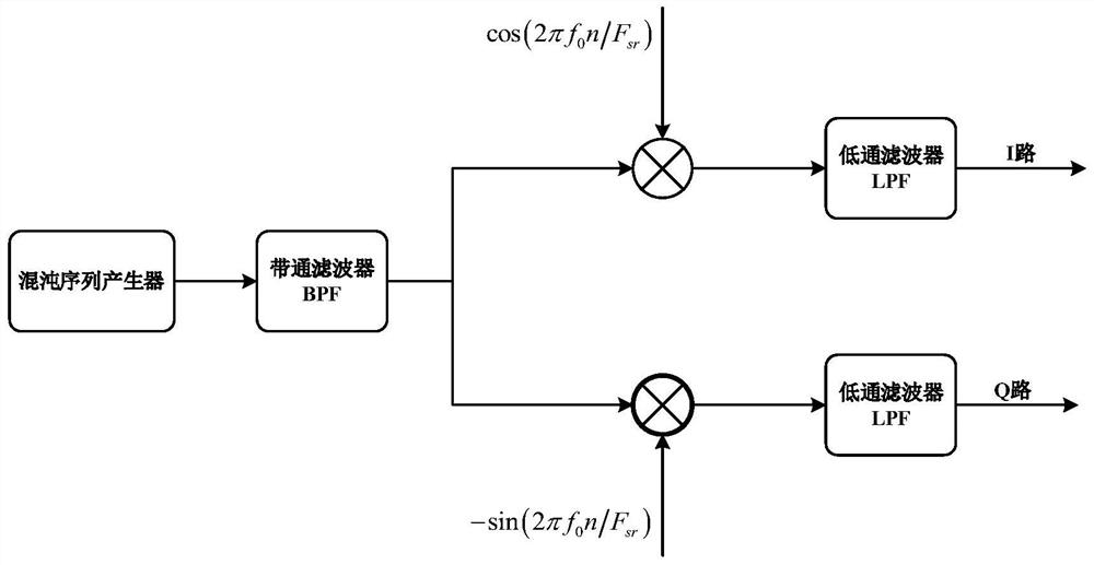
[0054] The baseband IQ circuit waveform generation module includes: a chaotic sequence generator, a band-pass filter, two frequency converters and two low-pass filters; wherein, the two frequency converters are connected in parallel, and each frequency converter is connected in series with a low-pass filter;

[0055] The chaotic sequence generator is used to generate a chaotic sequence and input it into a bandpass filter;

...

Embodiment 2

[0099] Based on the system of embodiment 1, embodiment 2 of the present application proposes a method for generating real-time generation of chaotic radar transmission signals based on FPGA, and the specific steps are as follows:

[0100] The FPGA generates chaotic radar baseband I and Q waveform data, and sends them to the 2 DAC chips at the same time;

[0101] The 2-way DAC chip performs digital-to-analog conversion on the I and Q waveform data to generate baseband I and Q analog waveforms, which are sent to the IQ modulator;

[0102] The IQ modulator combines the input I-channel and Q-channel analog waveforms with the intermediate frequency local oscillator signal LO2 to perform IQ modulation to generate an intermediate frequency chaotic signal, which is sent to the transmitting up-conversion module;

[0103] The transmitting up-conversion module mixes the intermediate frequency chaotic signal and the radio frequency local oscillator LO1 to generate the required radio frequ...


PUM


Abstract

The invention discloses an FPGA-based chaotic radar emission signal real-time generation system and method. The system comprises a baseband IQ path waveform generation module, a DAC module, an IQ modulator, an emission up-conversion module and a frequency source. The baseband IQ path waveform generation module is realized through an FPGA (Field Programmable Gate Array) and is used for respectively generating baseband I-path and Q-path waveform data of the chaotic radar; the DAC module is used for performing digital-to-analog conversion on the baseband I-path waveform data and the baseband Q-path waveform data to obtain baseband I-path analog waveforms and baseband Q-path analog waveforms; the IQ modulator is used for carrying out IQ modulation on I-path and Q-path analog waveforms of a baseband in combination with an intermediate-frequency local oscillator signal to generate an intermediate-frequency chaotic signal; the emission up-conversion module is used for mixing the intermediate frequency chaotic signal and the radio frequency local oscillator signal to generate a radio frequency chaotic signal; and the frequency source is used for providing a work clock, an intermediate frequency local oscillator signal and a radio frequency local oscillator signal of the FPGA.

Description

technical field [0001] The invention relates to the technical field of chaotic radar signal processing, in particular to an FPGA-based system and method for generating chaotic radar transmission signals in real time. Background technique [0002] Noise radar uses random or pseudo-random signals as the transmission waveform, which has been used in military and civilian fields (reference [1]: patent CN104777461A, a method and system for generating broadband chaotic radar signals with random carrier frequency hopping; Reference [2]: Krzysztof Kulpa, Signal Processing in Noise Waveform Radar, ISBN: 9781608076611). [0003] In noise radar, random or pseudo-random transmission signal generation is a key technology. Compared with ordinary thermal noise signals, chaotic signals are easier to generate and control. A chaotic signal is a pseudorandom signal generated by a deterministic system. The chaotic signal is very sensitive to the initial value, and a slight change in the init...

Claims


Application Information

Patent Timeline
Patent Type & Authority Applications(China)
IPC IPC(8): G01S7/41G01S7/282
CPCG01S7/41G01S7/282
Inventor 杨杰芳张云华李东唐月英石晓进
Owner NAT SPACE SCI CENT CAS
Learn More