Contact finger assembly

A technology of touch fingers and components, applied in the direction of contact meshing, contact shell/screen, etc., can solve the problems of small shrinkage force, poor contact between the contact finger and the contact, etc. Pressure, the effect of improving the flow capacity

Active Publication Date: 2021-06-08
PINGGAO GRP +1
View PDF13 Cites 0 Cited by
  • Summary
  • Abstract
  • Description
  • Claims
  • Application Information

AI Technical Summary

Problems solved by technology

[0005] The purpose of the present invention is to provide a contact finger assembly to solve the technical problem in the prior art that the contraction force at the upper end of the elastic contact sheet is small and the contact finger and the contact head cannot be in good contact and conduction.

Method used


Image

  • Contact finger assembly
  • Contact finger assembly
  • Contact finger assembly

Examples


specific Embodiment 1

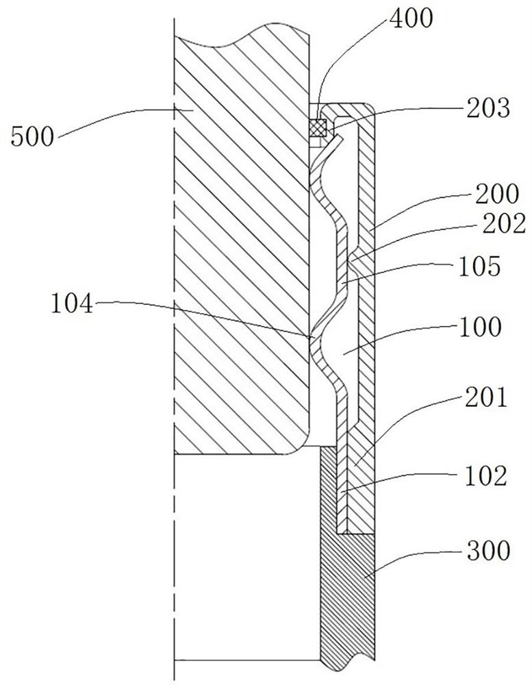
[0039] Such as Figure 1 to Figure 4 As shown, the finger assembly includes a support 300 , a contact finger 100 fixed on the support 300 , and a shield 200 , and the shield 200 covers the outside of the contact finger 100 .

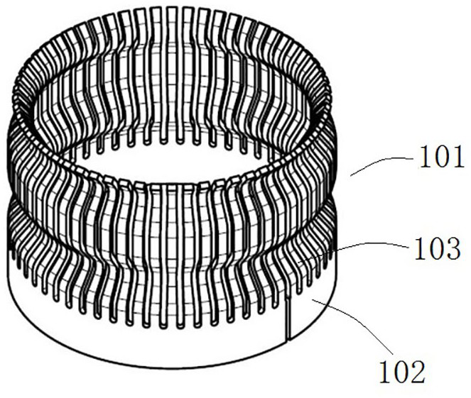
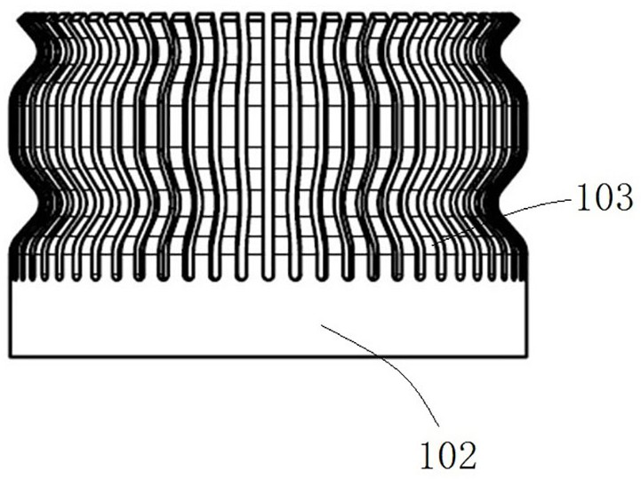
[0040] Such as figure 1 As shown, the support 300 is an annular conductor. The structure of the finger 100 is as follows: Figure 2 to Figure 4 As shown, the stylus 100 includes a stylus 101, and the stylus 101 is an integrally formed part with a gap, specifically, it can be formed by sheet metal or stamping from a plate or pipe. The contact finger 101 includes an arc-shaped base 102, and the central axis of the arc-shaped base 102 extends up and down. The contact finger 101 also includes a plurality of circumferentially spaced elastic contact pieces 103 above the arc-shaped base 102. The elastic contact pieces 103 The upper end is a cantilevered end, and the elastic contact piece 103 can elastically swing.

[0041] The specific structure of the elas...

specific Embodiment 2

[0048] Such as Figure 5 As shown, the difference from Embodiment 1 is that in Embodiment 1, there are two raised segments, while in this embodiment, the raised segments 104 have three layers arranged at intervals up and down, and two adjacent raised segments Straight line segments 105 are arranged between 104 . An annular protrusion 202 is provided on the shielding case 200 corresponding to each straight line segment 105 . In use, the three layers of raised segments 104 are in common contact with the contact 500 to achieve conductive communication.

[0049] In actual use, when designing the number of layers of the raised section 104 , it is necessary to take into account the contact pressure and the flow requirements to select reasonably. In actual use, the number of layers of the raised section 104 can be increased or decreased according to the actual situation.

Embodiment 1

[0051] In Embodiment 1, the stylus is composed of one stylus. In this embodiment, there may be two or more contact fingers.


PUM


Abstract

The invention belongs to the technical field of high-voltage switch parts, and particularly relates to a contact finger assembly. The contact finger assembly comprises a support and a contact finger. The support is an annular conductor; the contact finger comprises a contact finger sheet, the contact finger sheet comprises an arc-shaped base body, the arc-shaped base body is fixedly arranged on the support, the arc-shaped base body is provided with a central axis extending up and down, and the contact finger sheet further comprises an elastic contact sheet arranged above the arc-shaped base body; the elastic contact piece comprises a protruding section which protrudes towards the central axis and further comprises a straight line section which extends up and down, and the protruding section is used for elastic deformation to clamp the contact; the contact finger assembly further comprises a shielding cover arranged outside the contact fingers in a sleeving mode, the shielding cover comprises a press-fitting section on the lower portion, the press-fitting section is used for press-fitting the arc-shaped base body on the support, the shielding cover further comprises an annular protruding part located above the press-fitting section, and the annular protruding part is arranged on the inner side of the shielding cover in a protruding mode; and the annular protruding part is used for abutting against the straight line section of the elastic contact piece.

Description

technical field [0001] The invention belongs to the technical field of high-voltage switch parts, and in particular relates to a contact finger assembly. Background technique [0002] For the switching electrical appliance industry, the flow capacity is one of the important indicators of product performance. If the flow structure is unreasonable, the temperature rise of the product will be too high, the product flow capacity will decrease, and serious quality accidents will be caused; if the flow structure Complexity will lead to a large number of parts, complex assembly, and high manufacturing costs. The traditional contact structure includes petal contacts, forged self-supporting contacts, spring contacts, strap contacts and other contact structures. The head is either complicated to manufacture, has a large number of parts, or has high cost and poor scalability. Therefore, it is necessary to develop a new finger structure with simple structure, convenient assembly, good s...

Claims


Application Information

Patent Timeline
Patent Type & Authority Applications(China)
IPC IPC(8): H01H1/44H01H1/64
CPCH01H1/44H01H1/64
Inventor 徐仲勋李小欣魏魏李晓光李凯苑国旗杨继春宋继光李新刚王红超许东杰陈蕊司晓闯袁端鹏韩峰芦阳姚帅业赵华伟韩丽娟张佩范艳艳郭东方苗晓军庞亚娟
Owner PINGGAO GRP
Why Eureka
Try Eureka