Automatic household fan assembling equipment

An automatic assembly and fan technology, which is applied to workpiece clamping devices, manufacturing tools, etc., can solve the problems of inability to clamp the electric fan chassis and the support rod of the electric fan base, affecting the assembly efficiency of electric fans, and low efficiency of manual assembly. Achieve the effect of reducing labor intensity, improving stability and improving efficiency

Inactive Publication Date: 2021-06-11
伍晓明
View PDF5 Cites 0 Cited by
  • Summary
  • Abstract
  • Description
  • Claims
  • Application Information

AI Technical Summary

Problems solved by technology

[0003] However, the following difficult problems exist in the assembly of the current electric fan chassis and the electric fan base support bar. One, when the traditional electric fan chassis and the electric fan base support bar are assembled, it is necessary to manually use tools to clamp and position the electric fan base. Then use tools to rotate the electric fan threaded rod into the electric fan base support rod, the efficiency of manual assembly is low; two, when the existing electric fan is assembled, the electric fan chassis and the electric fan base support rod cannot be stably clamped , so that the electric fan base support rod and the electric fan chassis rotate when assembled, which affects the assembly efficiency of the electric fan

Method used


Image

  • Automatic household fan assembling equipment
  • Automatic household fan assembling equipment
  • Automatic household fan assembling equipment

Examples


Embodiment Construction

[0031] The embodiments of the present invention will be described in detail below with reference to the accompanying drawings, but the present invention can be implemented in many different ways defined and covered by the claims.

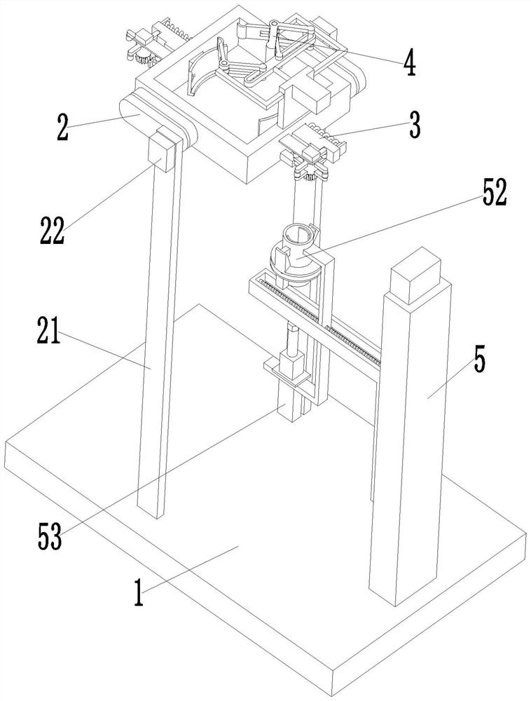
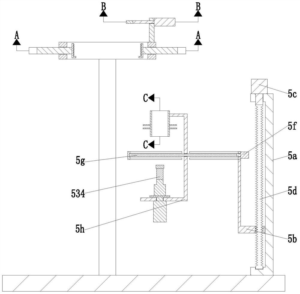
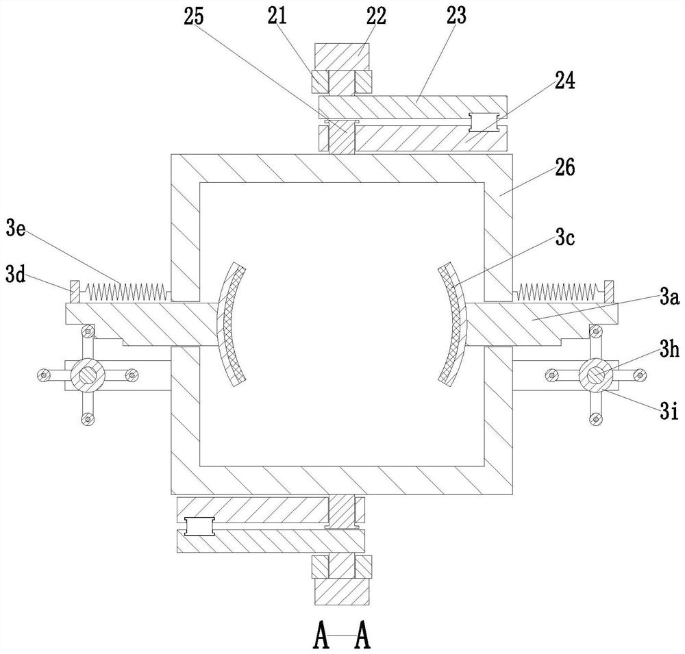
[0032] Such as Figure 1 to Figure 8 As shown, a household fan automatic assembly equipment includes a base plate 1, a moving device 2, a clamping device 3, a positioning device 4 and a lifting device 5. The left end of the base plate 1 is equipped with a moving device 2, and the moving device 2 is installed A clamping device 3 and a positioning device 4 are provided, and a jacking device 5 is installed on the right end of the bottom plate 1 .

[0033]The mobile device 2 includes a long bar 21, a No. 1 motor 22, a rotating bar 23, a driven bar 24, a T-shaped round bar 25 and a square frame 26, and the front and rear symmetrically mounted long bars 21 are arranged in the middle of the bottom plate 1. , a No. motor 22 is installed on the upper side o...


PUM


Abstract

The invention relates to automatic household fan assembling equipment which comprises a bottom plate, a moving device, a clamping device, a positioning device and a jacking device. The moving device is installed at the left end of the bottom plate, the clamping device and the positioning device are installed on the moving device, and the jacking device is installed at the right end of the bottom plate. According to the automatic household fan assembling equipment, the following problems existing when an existing electric fan base plate and an electric fan base supporting rod are assembled can be solved, firstly, when the traditional electric fan base plate and the electric fan base supporting rod are assembled, an electric fan base needs to be manually clamped and positioned through tools, then a tool is used for rotating an electric fan threaded rod into the electric fan base supporting rod, and the manual assembly efficiency is low; and secondly, when an existing electric fan is assembled, the electric fan base plate and the electric fan base supporting rod cannot be stably clamped, consequently the electric fan base supporting rod and the electric fan base plate rotate when being assembled, and the assembling efficiency of the electric fan is influenced.

Description

technical field [0001] The invention relates to the technical field of household appliances, in particular to automatic assembly equipment for household fans. Background technique [0002] An electric fan is referred to as an electric fan, also known as a fan or a fan. It is a household appliance that uses a motor to drive the fan blades to rotate to accelerate the circulation of air. It is mainly used for cooling, relieving heat and circulating air. Widely used in homes, classrooms, offices, shops, hospitals and hotels, etc. When assembling electric fans, it is necessary to install the electric fan base support rod on the electric fan chassis through the electric fan threaded rod, and carry out preliminary assembly work on the electric fan . [0003] However, the following difficult problems exist in the assembly of the current electric fan chassis and the electric fan base support bar. One, when the traditional electric fan chassis and the electric fan base support bar ar...

Claims


Application Information

Patent Timeline
Patent Type & Authority Applications(China)
IPC IPC(8): B25B11/00
CPCB25B11/00
Inventor 伍晓明伍哲楷包军平
Owner 伍晓明
Why Eureka
Try Eureka