Double-stage injection type brush handle injection molding equipment

A technology for injection molding equipment and brush handles, which is applied in the field of double-stage glue-injection brush handle injection molding equipment, which can solve problems such as lower product quality, mixed plastic colors, and inability to remove burrs, and achieve the effect of avoiding swinging

Inactive Publication Date: 2021-06-11
周立銮
View PDF0 Cites 0 Cited by
  • Summary
  • Abstract
  • Description
  • Claims
  • Application Information

AI Technical Summary

Problems solved by technology

[0002] The two-stage plastic injection type brush handle injection molding equipment is a special injection molding equipment that sets the two-color injection molding stages of the two-color toothbrush handle on the same machine. When making the toothbrush handle, it needs to make the main handle body first, and then the main handle that is not fully finalized The plastic injection molding of the auxiliary handle is carried out on the surface of the handle body, so that the splicing of the two-color toothbrush handle can be intersected when hot-melted to avoid the generation of gaps. When the toothbrush is produced by injection molding, in the process of secondary injection molding on the surface of the main handle body, because the main handle body needs to be subjected to secondary injection molding in a semi-molded state, it is impossible to remove the burr formed on the side by one injection molding. The burr of the handle body will swing during the secondary injection molding, which will cause the burr to be melted and absorbed by the hot melt plastic of the secondary injection molding, resulting in mixed color of the plastic of the secondary injection molding and lower product quality

Method used


Image

  • Double-stage injection type brush handle injection molding equipment
  • Double-stage injection type brush handle injection molding equipment
  • Double-stage injection type brush handle injection molding equipment

Examples


Embodiment 1

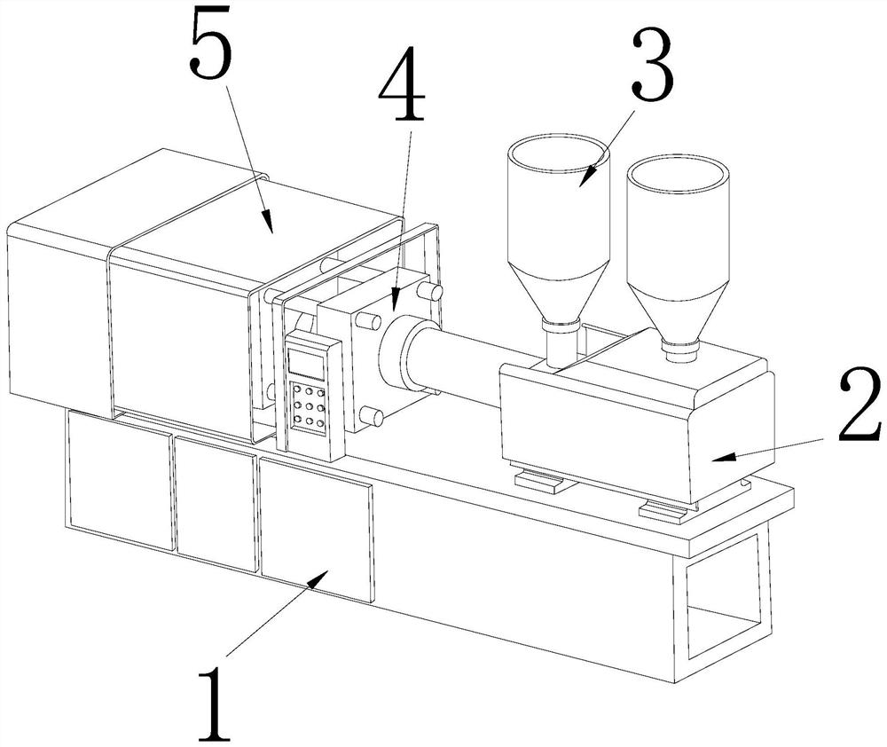
[0028] Such as Figure 1-Figure 6 As shown, the present invention provides a double-stage glue injection type brush handle injection molding equipment, the structure of which includes a machine base 1, a melting bin 2, a feeding bin 3, a pressing block 4, and a molding device 5. The melting bin 2 The bottom bolt is connected to the right side of the upper end of the machine base 1, the bottom end of the feeding bin 3 is embedded and connected to the upper end of the plastic melting bin 2, and the left side of the pressing block 4 is snapped and connected to the right side of the molding device 5 , the bottom end of the molding device 5 is fitted and connected to the upper left surface of the machine base 1 .

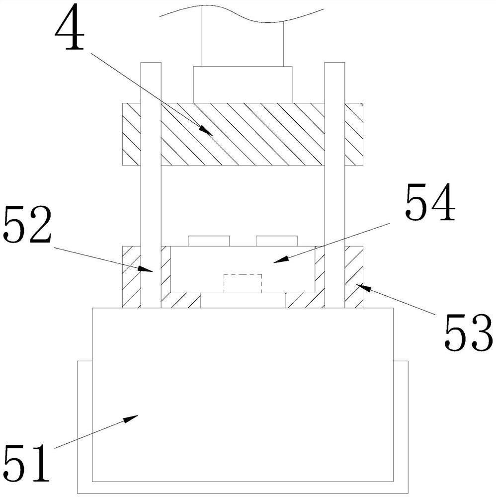
[0029] The molding device 5 includes a hydraulic seat 51, a lifting rod 52, a fixed seat 53, and a forming device 54. The outer periphery of the lower end of the lifting rod 52 is transitionally fitted inside the hydraulic seat 51, and the inner wall of the outer edge of...

Embodiment 2

[0037] Such as Figure 7-Figure 8 Shown:

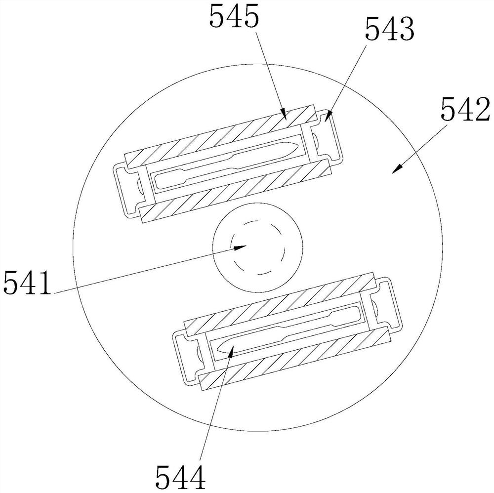
[0038] Wherein, the clamping block a54 includes a fitting piece b1, a block body b2, an elastic piece b3, and a breaking mechanism b4. On both sides of the upper surface of the body b2, the lower end of the breaking mechanism b4 is embedded and connected to the upper surface of the shrapnel b3. The shrapnel b3 is a semi-hollow arc-shaped sheet structure, which makes the two sides of the upper end break after being pressed. Mechanism b4 can be squeezed inward correctly.

[0039] Wherein, the breaking mechanism b4 includes a fixed column b41, a connecting block b42, a contact b43, a connecting shaft b44, and a cut-off piece b45. Connected to the center of the upper end of the connecting block b42, the connecting shaft b44 is fitted and connected to the inner edge of the side edge of the connecting block b42, the cut-off piece b45 is movably connected to the center of the front end of the connecting shaft b44, and the cut-off piece b45...


PUM


Abstract

The invention provides double-stage injection type brush handle injection molding equipment. The double-stage injection type brush handle injection molding equipment structurally comprises a machine base, a plastic melting bin, a feeding bin, a pressing-fit block and a molding device, the bottom end of the plastic melting bin is connected to the right side of the upper end of the machine base through bolts, the bottom end of the feeding bin is fixedly connected to the interior of the upper end of the plastic melting bin in an embedded mode, the interior of the left side of the pressing block is connected to the right side of the molding device in a clamped mode, and the bottom end of molding device is connected to the left side surface of upper end of base in an embedded mode. According to the double-stage injection type brush handle injection molding equipment, through extrusion of the upper end of a fixing device during secondary injection molding, an upper end piece of an elastic column forms downward extrusion force on the tail end of the right side of a connecting rod, then the connecting rod is driven by a torsion spring to rotate a clamping mechanism to clamp burrs of a main handle body, and under the buffering of a buffering mechanism in the interior of the clamping mechanism, the contact between the clamping block and the burrs is tighter, so that the burrs are further prevented from swinging in the secondary injection molding process.

Description

technical field [0001] The invention relates to the field of plastic injection, in particular to a double-stage plastic injection type brush handle injection molding equipment. Background technique [0002] The two-stage plastic injection type brush handle injection molding equipment is a special injection molding equipment that sets the two-color injection molding stages of the two-color toothbrush handle on the same machine. When making the toothbrush handle, it needs to make the main handle body first, and then the main handle that is not fully finalized The plastic injection molding of the auxiliary handle is carried out on the surface of the handle body, so that the splicing of the two-color toothbrush handle can be intersected when hot-melted to avoid the generation of gaps. When the toothbrush is produced by injection molding, in the process of secondary injection molding on the surface of the main handle body, because the main handle body needs to be subjected to sec...

Claims


Application Information

Patent Timeline
Patent Type & Authority Applications(China)
IPC IPC(8): B29C45/00B29C45/03B29C45/16B29C45/17B29C45/18B29C37/02
CPCB29C45/0053B29C45/03B29C45/16B29C45/17B29C45/1866B29C2045/0077
Inventor 周立銮
Owner 周立銮
Why Eureka
Try Eureka