
Gas-assisted mechanism and blowing method

A gas-assisted and gas-circuit technology, which is applied in the field of gas-assisted mechanisms and blowing, can solve the problems of high-pressure gas not being discharged in time, bursting, product strain, etc., and achieve the effect of avoiding pressure difference, not easy to strain, and avoiding bursting

Inactive Publication Date: 2021-06-11
NINGBO FANGZHENG TOOL
View PDF8 Cites 0 Cited by
  • Summary
  • Abstract
  • Description
  • Claims
  • Application Information

AI Technical Summary

Problems solved by technology

[0004] However, the existing gas-assisted mechanism has the following technical problems: because the high-pressure gas in the hollow part of the product after gas-assisted molding is not discharged in time, there is a large pressure difference between the internal and external environment of the product, which will cause the product to be strained or even burst. question

Method used


Image

  • Gas-assisted mechanism and blowing method
  • Gas-assisted mechanism and blowing method
  • Gas-assisted mechanism and blowing method

Examples


Embodiment 1

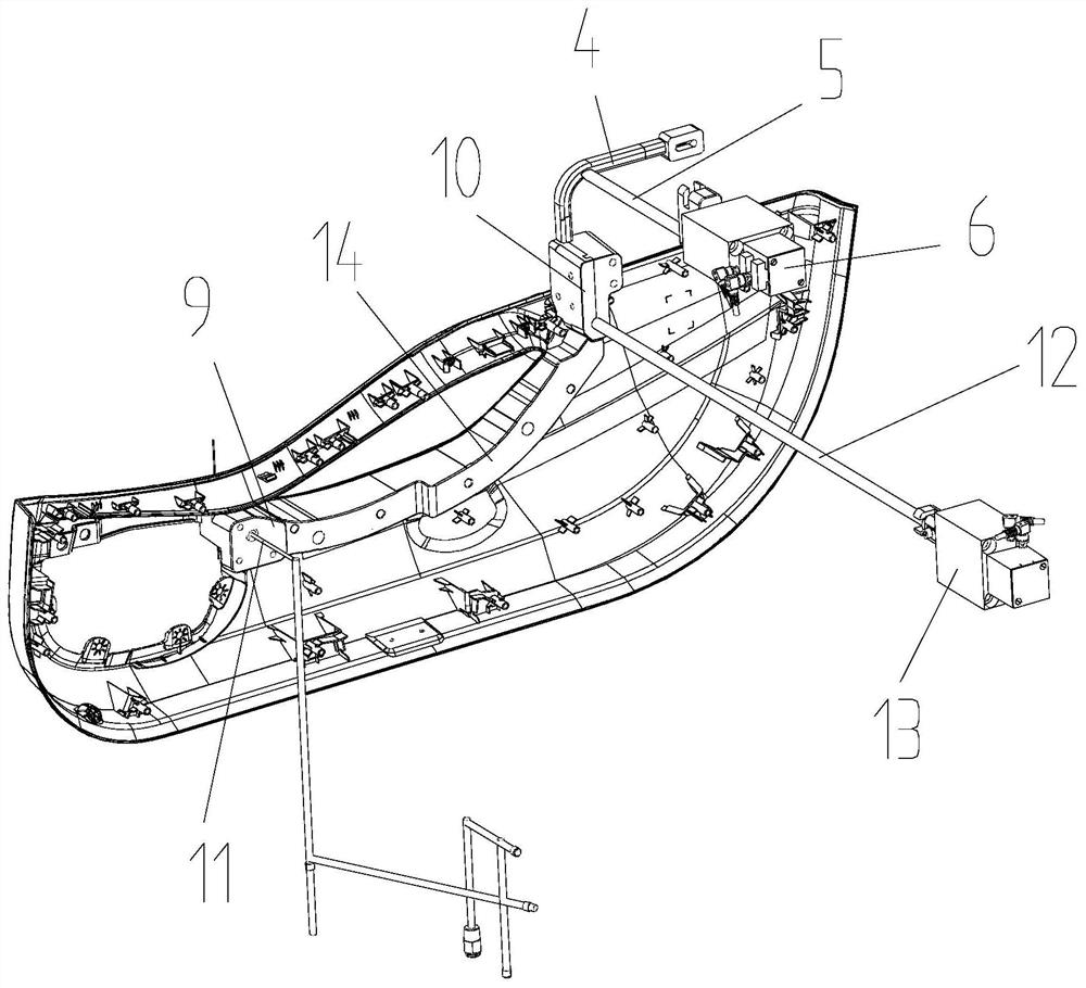
[0027] A gas-assisted mechanism, comprising a gas-assisted channel 3 with a feed port 1 at one end and a discharge port 2 at the other end, the discharge port 2 communicates with an overflow channel 4, and also includes a deflated ejector pin 5 and The first linear drive device 6, the deflated push rod 5 is arranged at the overflow channel 4, the first linear drive device 6 is connected with the deflated push rod 5, and is used for piercing or pulling out the deflated push rod 5 The overflow channel 4, the front end of the deflated mandrel 5 is tapered to form a knife portion 7, and the side of the deflated mandrel 5 near the knife portion 7 is cut off in the axial direction to form a vent channel 8 .

[0028] The gas-assisted mechanism of the present invention is provided with a deflated ejector pin 5 at the position where the overflow channel 4 is located, and uses the tapered knife portion 7 of the deflated ejector pin 5 to pierce into the cold material of the overflow chan...

Embodiment 2

[0032] A blowing method of a gas-assisted mechanism, the method is based on the gas-assisted mechanism in embodiment 1, and it comprises the following steps:

[0033] (1) Close the discharge port 2, and inject molten material through the feed port 1 for injection molding;

[0034] (2) Before the product is completely cooled after injection molding, open the discharge port 2, blow in nitrogen through the inlet needle 11, and blow out the excess material through the gas-assisted channel 3;

[0035] (3) The cold material blown out in the gas-assisted channel 3 overflows into the overflow channel 4, and the knife portion 7 of the deflated push rod 5 is driven by the first linear drive device 6 to penetrate the cold material in the overflow channel 4, so as to The piercing part of the cold material forms a weak point, and the high-pressure gas in the hollow part of the gas-assisted channel 3 is released from the weak point of the cold material, and is safely discharged out of the m...


PUM


Abstract

A gas-assisted mechanism comprises a gas-assisted channel, wherein one end of the gas-assisted channel is provided with a feeding port, the other end of the gas-assisted channel is provided with a discharging port, and the discharging port is communicated with an overflow channel. The gas-assisted mechanism is characterized by further comprising a gas release ejector rod and a first linear driving device, the gas release ejector rod is arranged at the overflow channel, the first linear driving device is connected with the gas release ejector rod, the first linear driving device is used for enabling the gas release ejector to penetrate into or pull out of the overflow channel, the front end of the gas release ejector rod is in a pointed cone shape and used for forming a cutter part, and a section, close to the cutter part, of the side face of the gas release ejector rod is cut off in the axial direction and used for forming the gas leakage channel. The gas-assisted mechanism is not prone to causing product strain, and can effectively solve the problem of burst. In addition, the invention further provides a blowing method of the gas-assisted mechanism.

Description

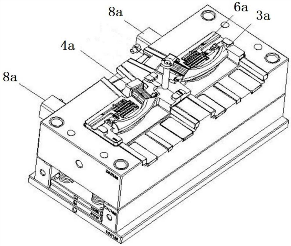
technical field [0001] The invention relates to the technical field of molds, in particular to a gas-assisted mechanism and a blowing method. Background technique [0002] Gas-assisted technology can be applied in almost all fields of plastic parts such as home appliances, automobiles, furniture, daily necessities, and office supplies. For example, in the injection molding process of automobile map bags or door panels, a gas-assisted mechanism is used to blow high-pressure gas (generally nitrogen) into the mold cavity after the molten plastic raw material enters the mold cavity. Compression molding, high-pressure gas can effectively distribute the molten plastic raw materials evenly to all corners of the mold cavity, so that the product has no miniature, the surface is smooth and beautiful, and it can also make the product hollow, saving materials and reducing production costs. [0003] An existing gas-assisted mechanism, its structure is as follows figure 1 As shown, it i...

Claims


Application Information

Patent Timeline
IPC IPC(8): B29C45/17
CPCB29C45/174
Inventor 应佳伟沈松静章泽锋王一栋
Owner NINGBO FANGZHENG TOOL
Learn More