Prestressed anchoring device for concrete bridge and construction method of prestressed anchoring device

An anchoring device and bridge construction technology, applied in bridge reinforcement, bridge, bridge maintenance, etc., can solve the problems that it is difficult to ensure that the tensile strength of carbon fiber cloth is fully utilized, the construction efficiency is low, and the structure of carbon fiber cloth tensile anchors is complicated.

Pending Publication Date: 2021-06-11
南京曼卡特科技有限公司
View PDF0 Cites 2 Cited by
  • Summary
  • Abstract
  • Description
  • Claims
  • Application Information

AI Technical Summary

Problems solved by technology

[0004] The purpose of the present invention is to provide a prestressed anchoring device for concrete bridges and its construction method, which can effectively solve the complex structure of the existing carbon fiber cloth tension anchor, troublesome construction and difficulty in ensuring that the tensile strength of carbon fiber cloth is fully utilized and construction efficiency low problem

Method used


Image

  • Prestressed anchoring device for concrete bridge and construction method of prestressed anchoring device
  • Prestressed anchoring device for concrete bridge and construction method of prestressed anchoring device
  • Prestressed anchoring device for concrete bridge and construction method of prestressed anchoring device

Examples


Embodiment 1

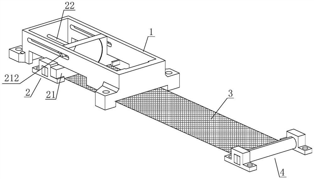
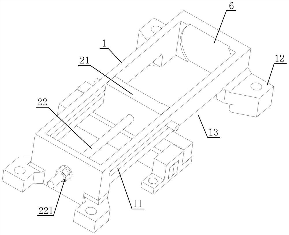
[0032] The technical scheme adopted in this embodiment is as follows: Figure 1~4 As shown, it is a prestressed anchoring device for a concrete bridge, which includes a frame assembly installed at the bottom of the bridge, a fixed part 4, a tension part 2, and a bridge construction between the fixed part 4 and the tension part 2. Surface carbon fiber cloth3.

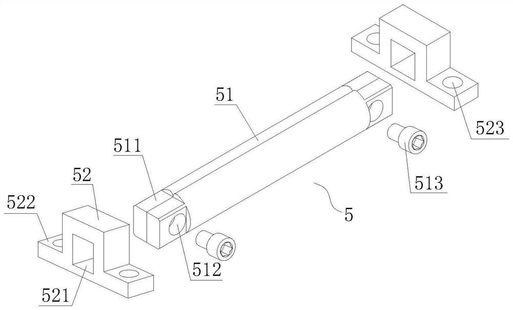
[0033] Specifically, both the fixed part 4 and the tension part 2 include such as image 3The clamping assembly 5 shown, the clamping assembly 5 includes a cloth clamping shaft 51 and a fixed base, two cloth clamping shafts 51 are provided, and the two clamping cloth shafts 51 are spliced ​​along the axial direction to form a cylinder, and the carbon fiber cloth 3 ends Clamped at the junction of the two clamping shafts 51; the fixed base is located at both ends of the two clamping shafts 51, clamping the spliced ​​two clamping shafts 51 and limiting the circumferential rotation of the two clamping shafts 51, the fixed b...

Embodiment 2

[0038] Present embodiment is the construction method of embodiment 1 concrete bridge prestressed anchorage device, comprises the following steps:

[0039] S1. Carry out pretreatment on the bridge construction surface, clamp one end of the carbon fiber cloth between the two clamping shafts of the fixed part, rotate one and a half weeks along the circumferential direction of the clamping shaft to fix the carbon fiber cloth on the clamping shaft, and then clamp the cloth Install fixed bases at both ends of the shaft, and anchor the fixed bases to the bridge construction surface through chemical anchor bolts;

[0040] S2. Clamp the other end of the carbon fiber cloth between the two clamping shafts of the tensioning part, and rotate the clamping shaft for one and a half weeks to fix the carbon fiber cloth on the clamping shaft, and then install a fixed base at both ends of the clamping shaft , place the tensioned top plate on the anchoring flange of the fixed base, and finally ins...


PUM


Abstract

The invention relates to a prestressed anchoring device for a concrete bridge and a construction method of the prestressed anchoring device. The anchoring device comprises a rectangular frame, a fixing part, a tensioning part and carbon fiber cloth which is located between the fixing part and the tensioning part and tightly attached to a bridge construction face. Kidney-shaped through holes are formed in the two sides of the rectangular frame in the length direction of the rectangular frame, the tensioning part is located in the inner side of the rectangular frame and slidably arranged in the length direction of the rectangular frame through the kidney-shaped through holes, and the fixing part is anchored to a bridge construction face on the length extension line of the rectangular frame. According to the construction method, the fixing part is anchored firstly, then a jack is arranged between the tensioning part and the rectangular frame, the jack is used for pushing the tensioning part to tension the carbon fiber cloth, and after the carbon fiber cloth is tensioned in place, the tensioning part is fixed to the bridge installation face; and after the carbon fiber cloth is pasted, the fixing part, the rectangular frame and the tensioning part are detached. The problems that an existing carbon fiber cloth tensioning anchorage device is complex in structure and troublesome in construction, the tensile strength of the carbon fiber cloth is difficult to guarantee, and the construction efficiency is low can be effectively solved.

Description

technical field [0001] The invention relates to the technical field of concrete bridge reinforcement, in particular to a prestressed anchoring device for a concrete bridge and a construction method thereof. Background technique [0002] Reinforced concrete bridges account for a large proportion of existing bridges in our country, but their technical status is poor. On the one hand, due to the low design standards, bridges built according to the design standards announced by the Ministry of Communications in 1972 and 1982 can basically meet the requirements of the recent traffic. , before that, especially the bridges built in the late 1950s and 1960s, most of the bridges have been subjected to vehicle loads exceeding the design load for a long time; on the other hand, due to problems in bridge design, construction, maintenance, management, surrounding environment, etc. Accidental disasters encountered during use, such as earthquakes, floods, accidental impacts, etc., lead to ...

Claims


Application Information

Patent Timeline
Patent Type & Authority Applications(China)
IPC IPC(8): E01D22/00E01C5/12
CPCE01C5/12E01D22/00
Inventor 徐宝余葛亮亮
Owner 南京曼卡特科技有限公司
Why Eureka
Try Eureka