
crankshaft and compressor

A compressor and crankshaft technology, applied in the field of compressors, can solve problems such as friction and wear, and achieve the effects of improving performance, reducing wear, reducing contact and direct friction

Active Publication Date: 2022-05-27
ZHUHAI GREE REFRIGERATION TECH CENT OF ENERGY SAVING & ENVIRONMENTAL PROTECTION
View PDF5 Cites 2 Cited by
  • Summary
  • Abstract
  • Description
  • Claims
  • Application Information

AI Technical Summary

Problems solved by technology

The thrust surface not only bears its own weight but also bears the weight of the motor rotor at the upper end of the crankshaft, so there is serious friction and wear between the thrust surface and the lower flange

Method used


Image

  • crankshaft and compressor
  • crankshaft and compressor
  • crankshaft and compressor

Examples


Embodiment Construction

[0029] The technical solutions in the embodiments of the present invention will be clearly and completely described below with reference to the accompanying drawings in the embodiments of the present invention. Obviously, the described embodiments are only some, but not all, embodiments of the present invention. The following description of at least one exemplary embodiment is merely illustrative in nature and is in no way intended to limit the invention, its application, or uses. Based on the embodiments of the present invention, all other embodiments obtained by those of ordinary skill in the art without creative efforts shall fall within the protection scope of the present invention.

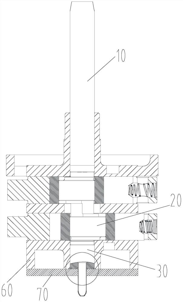
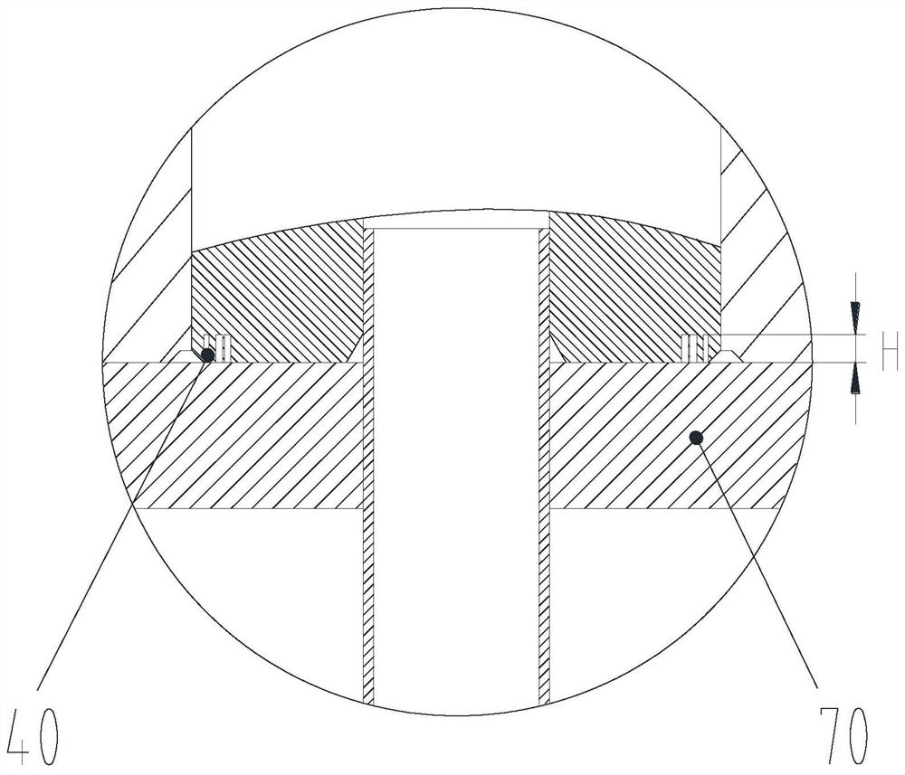
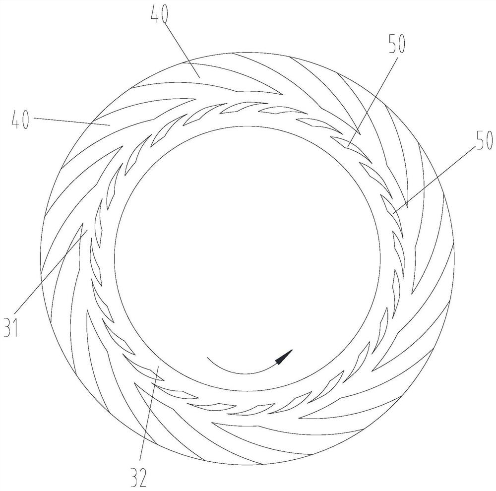
[0030] like Figure 1 to Figure 9 As shown, the embodiment of the present invention provides a crankshaft, the crankshaft includes a long shaft 10, an eccentric portion 20 and a short shaft 30 connected in sequence, the end face of the short shaft 30 has a thrust surface, and the thrust surf...


PUM


Abstract

The invention provides a crankshaft and a compressor. The crankshaft includes a long shaft, an eccentric part and a short shaft connected in sequence. The end face of the short shaft is a thrust surface, and the thrust surface has an outer annular lubricating area and an inner annular lubricating area. The lubricating area is set around the inner annular lubricating area; among them, there are multiple outer lubricating grooves in the outer annular lubricating area, and the plurality of outer lubricating grooves are arranged at intervals along the circumference of the outer annular lubricating area; there are multiple inner lubricating grooves in the inner annular lubricating area , a plurality of inner lubricating grooves are arranged at intervals along the circumference of the inner annular lubricating area. When in use, the thrust surface of the crankshaft cooperates with the mating surface of the mating parts. When the crankshaft rotates, the gas and lubricating oil located outside the thrust surface enter the thrust surface and the mating surface through multiple external lubrication grooves and multiple internal lubrication grooves. Between them, a layer of fluid film is formed, which can avoid or reduce the contact and direct friction between the thrust surface and the mating surface, thereby reducing the wear of the crankshaft and mating parts, and improving the performance of the compressor using the above structure.

Description

technical field [0001] The present invention relates to the technical field of compressors, and in particular, to a crankshaft and a compressor. Background technique [0002] During the operation of the rotary compressor, the eccentric part of the crankshaft has a thrust surface, and the thrust surface provides axial support for the crankshaft assembly. When the crankshaft rotates, sliding friction is formed between the thrust surface of the crankshaft and the thrust block. The thrust surface not only bears its own weight but also the weight of the motor rotor at the upper end of the crankshaft, so there is serious friction and wear between the thrust surface and the lower flange. Therefore, during the operation of the compressor, it is necessary to reduce the wear between the crankshaft thrust surface and the thrust block and ensure the stable working state of the crankshaft. SUMMARY OF THE INVENTION [0003] The invention provides a crankshaft and a compressor to reduce...

Claims


Application Information

Patent Timeline
Patent Type & Authority Patents(China)
IPC IPC(8): F04C29/00F04C29/02
CPCF04C29/00F04C29/02F04C2240/601
Inventor 闫鹏举张心爱张大鹏黄纯浚
Owner ZHUHAI GREE REFRIGERATION TECH CENT OF ENERGY SAVING & ENVIRONMENTAL PROTECTION
Learn More