
Flow valve used on flow control device

A technology of a flow control device and a flow valve, which is applied in the field of flow valves, can solve problems such as unstable valve core, broken valve core, poor stability, etc., and achieve stable operation and solve the effect of unstable valve core

Inactive Publication Date: 2021-06-11
黄佳翔
View PDF0 Cites 0 Cited by
  • Summary
  • Abstract
  • Description
  • Claims
  • Application Information

AI Technical Summary

Problems solved by technology

[0006] The purpose of the present invention is to provide a flow valve used on a flow control device to solve the above-mentioned background art. In the prior art, the spool is actually very unstable, and it is easy to move, thereby limiting the flow cross section of the hydraulic oil flow. It is easy to change, which will lead to fluctuations in the action of the actuator and poor stability; a slight fluctuation in the current passed into the coil used to form the electromagnetic force will break the balance of the spool, thus preventing the flow of hydraulic oil Keep the problem at a low and constant amount

Method used


Image

  • Flow valve used on flow control device
  • Flow valve used on flow control device
  • Flow valve used on flow control device

Examples


Embodiment Construction

[0030] In order to make the purpose, technical solutions and advantages of the embodiments of the present invention clearer, the technical solutions in the embodiments of the present invention will be clearly and completely described below in conjunction with the accompanying drawings in the embodiments of the present invention. Obviously, the described embodiments It is some embodiments of the present invention, but not all of them. Based on the implementation manners in the present invention, all other implementation manners obtained by persons of ordinary skill in the art without creative efforts fall within the protection scope of the present invention. Accordingly, the following detailed description of the embodiments of the invention provided in the accompanying drawings is not intended to limit the scope of the claimed invention, but merely represents selected embodiments of the invention. Based on the implementation manners in the present invention, all other implement...


PUM


Abstract

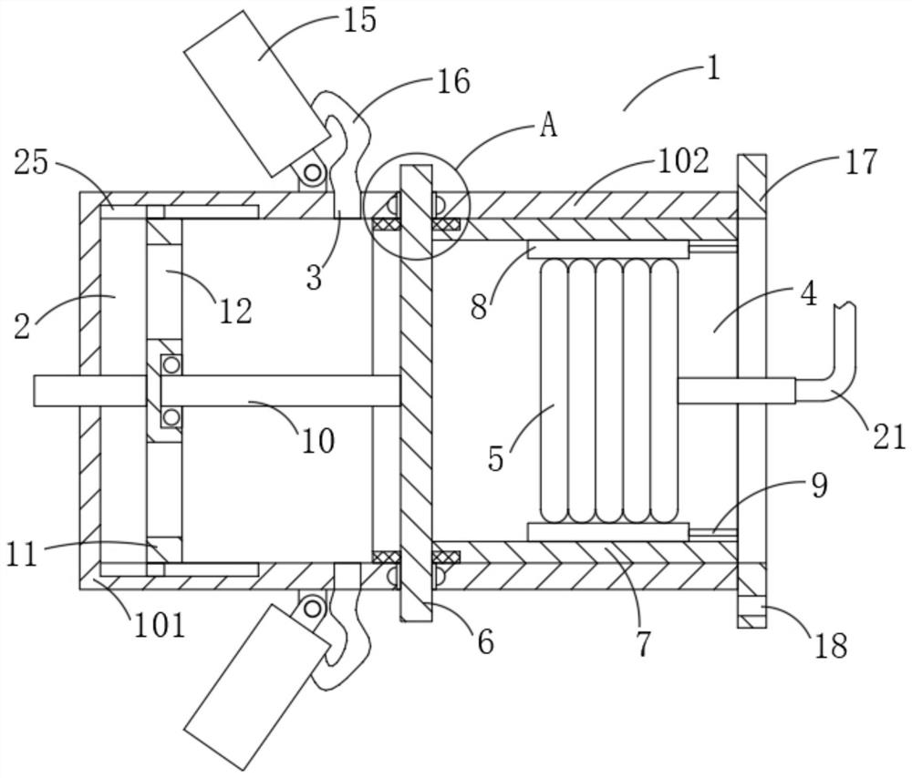
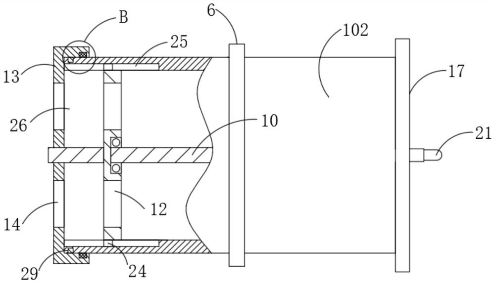
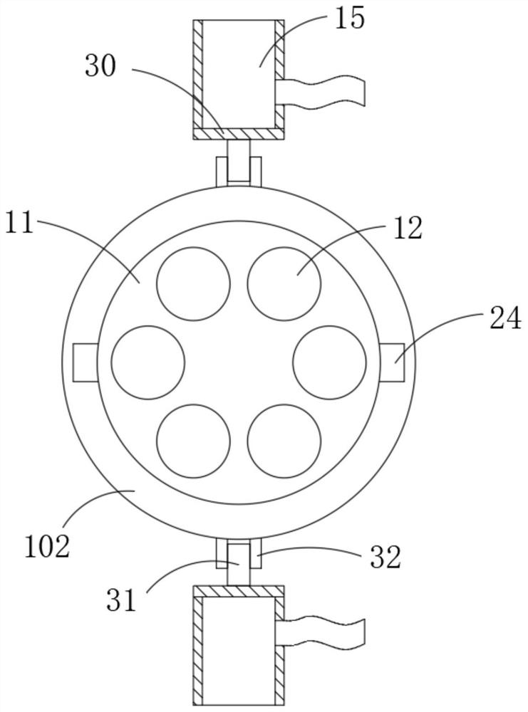
The invention discloses a flow valve used on a flow control device. The flow valve comprises a valve body, a first outlet and two groups of second outlets, an inlet is formed in one side of the valve body, an air bag is slidably installed on the side, close to the inlet, in the valve body, a driving plate is rotatably installed in the middle of the valve body, and an inner threaded sleeve is fixedly connected to the side, close to the inlet, of the driving plate; an outer threaded sleeve is arranged between the air bag and the inner threaded sleeve in a threaded mode, a guide rod is connected between the outer threaded sleeve and the inlet, a push rod is fixedly connected to the side, away from the inner threaded sleeve, of the driving plate, a baffle is slidably installed in the valve body, and the end, away from the driving plate, of the push rod is rotationally connected with the baffle through a bearing; and six groups of first via holes are annularly formed in the baffle at equal intervals, the first outlet is formed in the side, away from the inlet, of the valve body, a gland is rotationally installed outside the first outlet, second via holes are annularly formed in the gland at equal intervals, safety control over the valve body is guaranteed, and the problems that a valve element is unstable and easy to move are solved.

Description

technical field [0001] The invention belongs to the field of valves, in particular to a flow valve used in a flow control device. Background technique [0002] The flow valve is mostly used to control the action speed of the actuator, for example, to control the extension speed of the piston rod of the oil cylinder. Specifically, the flow valve has an oil inlet connected to the power element, an oil outlet connected to the actuator, a valve seat and a valve core; a diversion hole is opened on the valve seat; the valve core is used to block the diversion hole or open the diversion hole to realize the communication between the oil inlet and the oil outlet. The spool moves to change the opening of the diversion hole (also known as changing the flow section that limits the flow of hydraulic oil), thereby changing the flow of hydraulic oil through the diversion hole (or the hydraulic pressure that enters the chamber of the actuator) oil flow) to change the action speed of the a...

Claims


Application Information

Patent Timeline
Patent Type & Authority Applications(China)
IPC IPC(8): F16K3/08F16K3/314
CPCF16K3/08F16K3/314
Inventor 黄佳翔
Owner 黄佳翔
Learn More