
Construction method of underground diaphragm wall with movable door sealing mechanism and reserved opening in the wall

A technology of reserving holes and sealing doors, applied in infrastructure engineering, artificial islands, earthwork drilling, etc., can solve problems such as reducing structural safety, low construction efficiency, increasing tool wear, etc., to reduce the risk of mechanical failure, Save material and labor, ensure strength and stable effect

Active Publication Date: 2015-08-19
TONGJI UNIV
View PDF2 Cites 0 Cited by
  • Summary
  • Abstract
  • Description
  • Claims
  • Application Information

AI Technical Summary

Problems solved by technology

[0004] (1) Manual operation, high risk, low construction efficiency, long construction period, increasing the total construction period;
[0005] (2) Manual chiseling operation, the operation cannot be accurately guaranteed, and construction impact loads are generated on the structure, which increases the damage of the wall structure and reduces the safety of the structure;
[0006] (3) Due to the low efficiency of manual work, the long-term exposure of the air surface of the soil layer after chiseling increases the risk of soil instability and groundwater gushing;
[0007] (4) For the chiseling of concrete in and out of the shield tunnel, generally a certain thickness of the wall is left to be cut by the shield cutter head, which increases the wear of the cutter and increases the risk of shield tunneling;
[0008] (5) In order to ensure the stability of the soil layer, the thickness of the ground reinforcement is generally relatively large, which increases the project cost;
[0009] (6) Chisel away the large volume of reinforced concrete, which is not conducive to the energy saving and environmental protection of engineering construction
[0011] (1) GFRP-reinforced concrete structure is not widely used in China, and its mechanical deformation properties are not fully grasped, and the technical application has certain risks;
[0012] (2) When the shield enters and exits the hole, the concrete must be cut directly, which will cause great damage to the knife;
[0013] (3) Cutting away a large amount of GFRP reinforced concrete also does not meet the requirements of energy saving and environmental protection in construction

Method used


Image

  • Construction method of underground diaphragm wall with movable door sealing mechanism and reserved opening in the wall
  • Construction method of underground diaphragm wall with movable door sealing mechanism and reserved opening in the wall
  • Construction method of underground diaphragm wall with movable door sealing mechanism and reserved opening in the wall

Examples


Embodiment 1

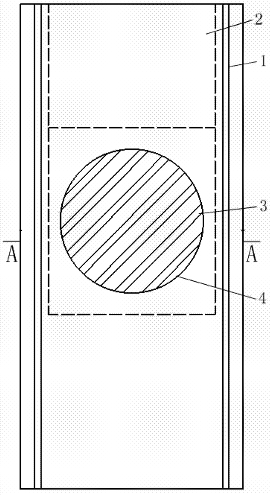
[0058] A movable door sealing mechanism in the wall, such as figure 1 and figure 2 As shown, the movable door sealing mechanism 2 in the wall is arranged on the outside of the continuous wall 1. The movable door sealing mechanism in the wall includes a door sealing main structure and at least one door sealing sub-component. The door sealing section and the connecting door sealing section are connected by connecting joints.

[0059] The sub-components of door sealing include post-tensioning anti-pressure loading device, door sealing chute, water sealing device for door sealing seam, contact surface friction reduction device, liquid injection pipeline, auxiliary door sealing lifting device, door sealing mechanical deformation and water seepage monitoring device, post-tensioning The anti-pressure loading device is installed in the middle of the door sealing section of the hole, the door sealing chute is set around the main structure of the door sealing, and the water sealing de...

Embodiment 2

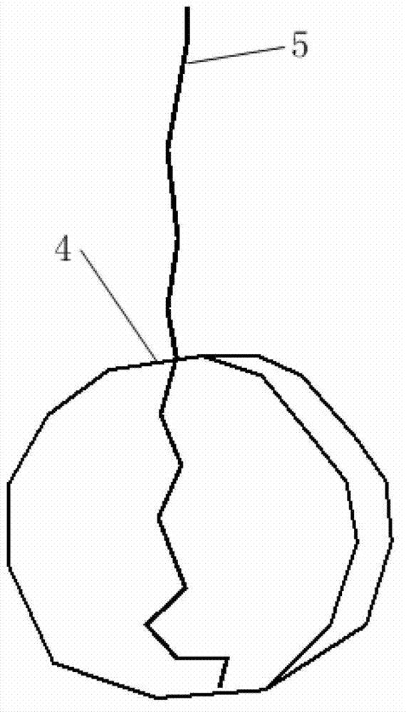
[0076] A construction method for an underground diaphragm wall with a reserved opening and a movable door sealing mechanism device in the wall, including a diaphragm wall width 1 and a movable door sealing device 2, the designed geometric dimensions and stratum parameters, groundwater, foundation pit excavation depth, and opening position And related to the characteristics of the structural materials used, when the thickness of the wall exceeds the thickness of the ordinary wall, over-excavation must be carried out; the reinforcement reinforcement in the wall structure 6 of the continuous wall must be encrypted at the position of the hole circle to ensure that the wall width of the hole is not affected. The force is stable, a circle of steel plates is pre-buried around the hole and a connecting flange is provided to facilitate the connection between other components and the hole ring and strengthen the overall stability of the hole ring; the reserved hole 3 can be round or squar...


PUM


Abstract

The invention relates to a wall concealed movable door sealing mechanism and a construction method for an underground continuous wall with a reserved hole. The wall concealed movable door sealing mechanism comprises a door sealing main body structure and at least one door sealing subpart, wherein the door sealing subpart comprises a post tensioning back pressure loading device, a door sealing sliding chute, a door sealing seam water stop device, a contact surface friction device, a liquid injection pipeline, a door sealing auxiliary lifting device and a door sealing mechanical deformation and water seepage monitoring device; before a steel reinforcement cage is placed in position, a sack is arranged in the reserved hole of the steel reinforcement cage in advance, the wall concealed movable door sealing mechanism is placed in position by hoisting while the steel reinforcement cage is placed in position by hoisting, concrete is poured after the hoisting is finished, the continuous wall is formed through pouring, the sack is recovered when the excavation of a foundation pit starts after the continuous wall is formed, and then the underground continuous wall with the reserved hole is formed. Compared with the prior art, the wall concealed movable door sealing mechanism and the construction method for the underground continuous wall with the reserved hole have the advantages that the wall body of the continuous wall is not needed to be broken down, and the continuous operation of tunnel and underground engineering construction on passing through continuous walls is realized.

Description

technical field [0001] The invention relates to a construction method and a door sealing device for an underground diaphragm wall requiring openings, in particular to a movable door sealing mechanism in the wall and a construction method for an underground diaphragm wall with a reserved hole, which is suitable for the shield tunnel engineering shield tunnel entry and exit underground Opening of diaphragm walls and opening of diaphragm walls in other underground works. Background technique [0002] For the opening of the diaphragm wall when the shield enters and leaves the hole in the shield tunneling project and the opening of the diaphragm wall in other underground projects, the existing technology is mainly to manually chisel it; Local GFRP (Glass-Fiber-Reinforced polymer, glass fiber reinforced polymer) reinforced underground diaphragm wall + shield direct cutting construction technology can be used. [0003] 1. The specific method of manual chiseling is as follows: befo...

Claims


Application Information

Patent Timeline
Patent Type & Authority Patents(China)
IPC IPC(8): E21D9/14E02D29/02
Inventor 廖少明徐永门燕青
Owner TONGJI UNIV
Learn More