
Monitoring camera mounting system

A monitoring camera and installation system technology, which is applied in the field of monitoring cameras, can solve problems such as shortening the service life of equipment, cumbersome operation procedures, and corrosion of support columns, and achieves simplified installation and disassembly procedures, firm fixing process, and a wide range of installation Effect

Inactive Publication Date: 2021-06-11
苏州市佳信美智能装备有限公司
View PDF5 Cites 2 Cited by
  • Summary
  • Abstract
  • Description
  • Claims
  • Application Information

AI Technical Summary

Problems solved by technology

The existing monitoring camera is fixed on the support column by multiple screws. Since multiple screws need to be operated cyclically during the installation and disassembly process, there are problems of cumbersome operation and low efficiency. At the same time, the existing The camera is fixed on the supporting column by screws, which requires drilling and destroying the supporting column. After a long time of use, it is easy to cause the supporting column to rust, thereby shortening the service life of the equipment

Method used


Image

  • Monitoring camera mounting system
  • Monitoring camera mounting system
  • Monitoring camera mounting system

Examples


Embodiment Construction

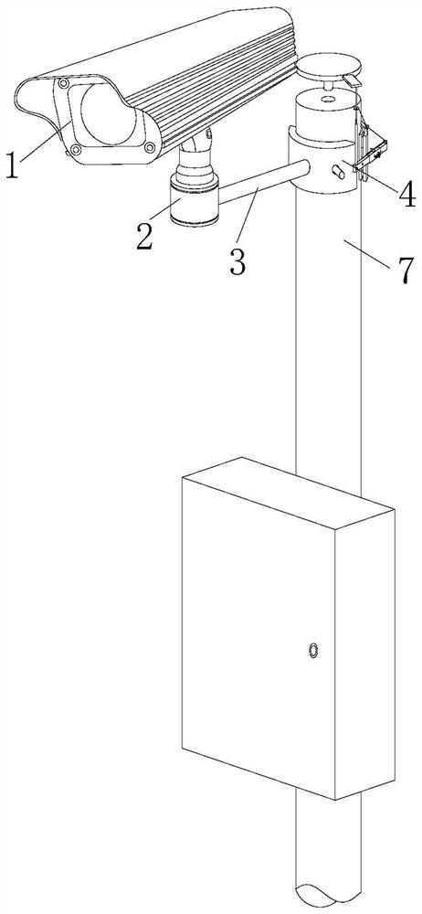
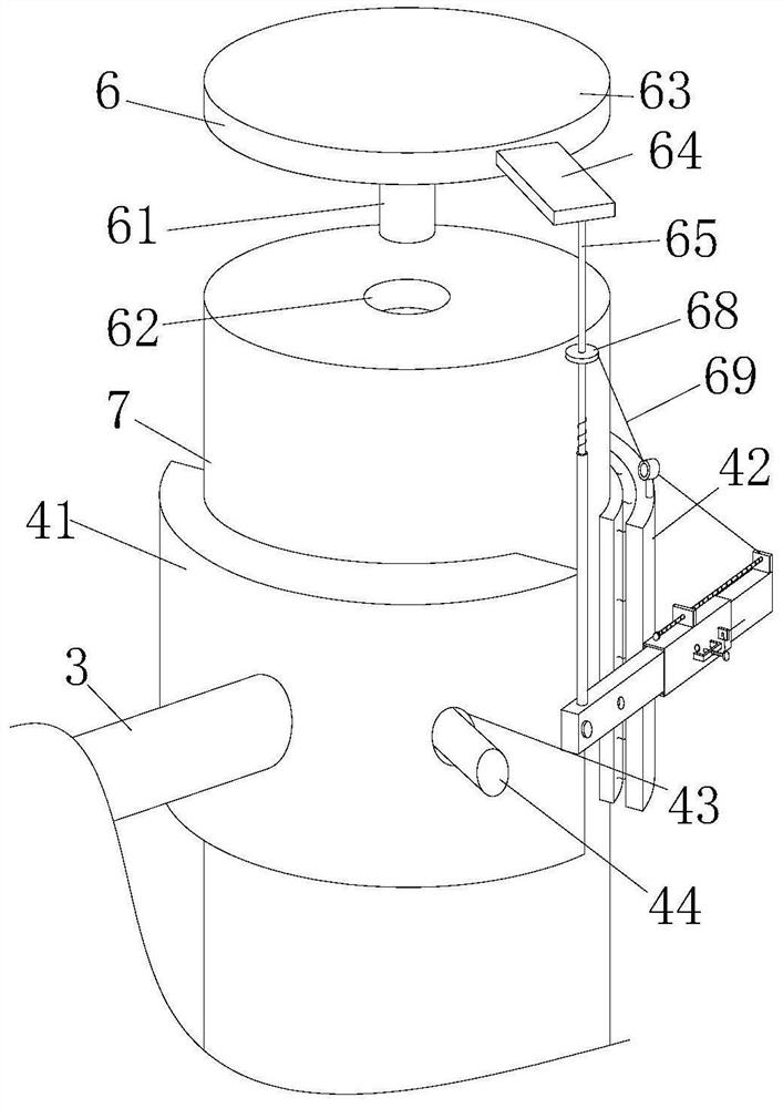
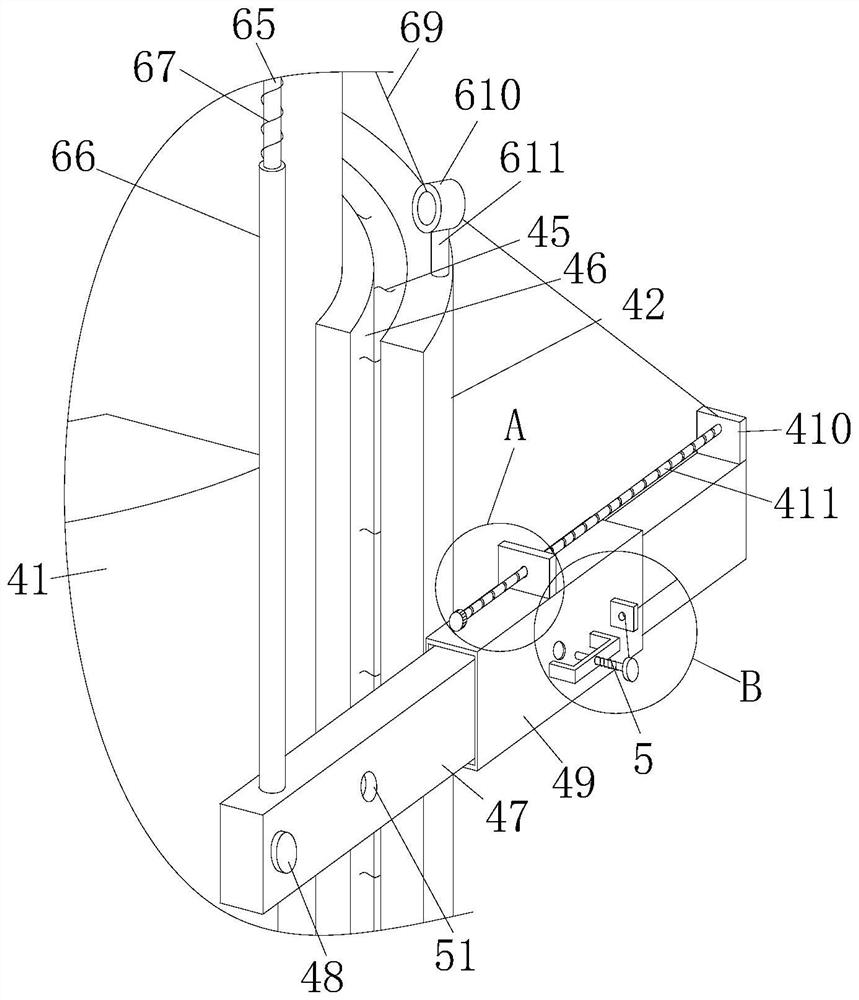
[0030] Attached below Figure 1-5 The present invention is further described with embodiment:

[0031] A monitoring camera installation system, comprising a monitoring camera body 1, a supporting rotating base 2 and a fixed connecting rod 3, the monitoring camera body 1 is arranged on the supporting rotating base 2, and the side wall of the supporting rotating base 2 is fixedly connected with Fix the connecting rod 3, the free end of the fixed connecting rod 3 is fixedly connected on the fixing mechanism 4, and the fixing mechanism 4 is detachably arranged outside the fixed support column 7, by optimizing the fixing method of the existing monitoring camera body 1 in the present invention, Specifically, the monitoring camera body 1 is fixedly arranged on the fixed support column 7 by avoiding punching holes, which can effectively avoid direct damage to the fixed support column 7, thereby making the service life of the equipment high and long, and the optimized fixed structure ...


PUM


Abstract

The invention relates to a monitoring camera mounting system. The system comprises a monitoring camera body, a support rotating base and a fixed connecting rod, the monitoring camera body is arranged on the support rotating base, the side wall of the support rotating base is fixedly connected with the fixed connecting rod, a free end of the fixed connecting rod is fixedly connected to a fixing mechanism, and the fixing mechanism is detachably arranged outside a fixed supporting column. According to the system, a fixing mode of an existing monitoring camera body is optimized, specifically, the monitoring camera body is fixedly arranged on the fixed supporting column in a punching-free mode, in this way, direct damage to the fixed supporting column can be effectively avoided, the service life of a device is prolonged, and the optimized fixing structure is simple in structure, reasonable in design and easy to operate, can achieve the effects of saving time and labor and facilitating operation in the actual operation process, and meanwhile can prolong the service life of the device, thereby having higher practical value in actual application.

Description

technical field [0001] The invention relates to the technical field of monitoring cameras, in particular to a monitoring camera installation system. Background technique [0002] The surveillance camera is a semiconductor imaging device. The image is generated from the CCD camera. It is mainly used for image acquisition at the front end of the surveillance system. It has the advantages of high sensitivity, anti-glare, small distortion, small size, long life, and anti-vibration. When existing monitoring cameras are in use, they are mostly fixed on high places by support columns, so that the detection range is wider. The existing monitoring camera is fixed on the support column by multiple screws. Since multiple screws need to be operated cyclically during the installation and disassembly process, there are problems of cumbersome operation and low efficiency. At the same time, the existing The camera is fixed on the supporting column by screws, which requires drilling and des...

Claims


Application Information

Patent Timeline
Patent Type & Authority Applications(China)
IPC IPC(8): F16M13/02F16M11/08H04N5/225H04N7/18
CPCF16M13/02F16M11/08F16M2200/028H04N7/18H04N23/00
Inventor 李云松
Owner 苏州市佳信美智能装备有限公司
Learn More