Level conversion circuit

A technology of conversion circuit and level shift circuit, which is applied in the direction of logic circuit connection/interface layout, logic circuit coupling/interface using field effect transistors, etc. Interval width, solving the effect of low accuracy, and solving the effect of insufficient hysteresis interval width

Pending Publication Date: 2021-06-11
南京国微电子有限公司 +1
View PDF0 Cites 0 Cited by
  • Summary
  • Abstract
  • Description
  • Claims
  • Application Information

AI Technical Summary

Problems solved by technology

However, the upper and lower threshold voltages of this type of hysteresis comparison circuit are greatly affected by t...

Method used


Image

  • Level conversion circuit
  • Level conversion circuit
  • Level conversion circuit

Examples


Embodiment Construction

[0029] In order to make the purpose, technical solution and advantages of the present application clearer, the present application will be further described in detail below in conjunction with the accompanying drawings and embodiments. It should be understood that the specific embodiments described here are only used to explain the present application, and are not intended to limit the present application.

[0030] In one embodiment, such as Figure 4 As shown, a level conversion circuit is provided, including: an input voltage comparison circuit unit 1, a level shift circuit unit 2, a hysteresis feedback circuit unit 3 and an inverting logic output circuit unit 4; the signal of the input voltage comparison circuit unit 1 The output end is connected with the signal input end of the level shift circuit unit 2, and the signal output end of the level shift circuit unit 2 is respectively connected with the signal input end of the hysteresis feedback circuit unit 3 and the signal i...


PUM


Abstract

The invention relates to a level conversion circuit. The circuit is characterized in that an input voltage comparison circuit unit compares an input first logic signal with a reference voltage and outputs a second logic signal, the second logic signal is input to a level shift circuit unit of a source follower structure, and the level shift circuit unit performs level shift on the second logic signal and outputs a third logic signal; the third logic signal is input to a hysteresis feedback circuit unit of an active resistance voltage division structure, the hysteresis feedback circuit unit feeds back the third logic signal to a reference voltage end, the phase of the third logic signal is adjusted by an anti-phase logic output circuit unit, and a fourth logic signal is output; the third logic signal is fed back to the reference voltage end of the input voltage comparison circuit unit, when conditions such as temperature and power supply voltage change, the hysteresis interval width can be effectively guaranteed, the fluctuation range of upper and lower threshold voltage is reduced, and the problems that the hysteresis interval width is not enough and the accuracy is low are solved.

Description

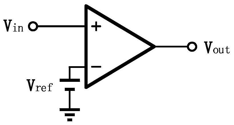
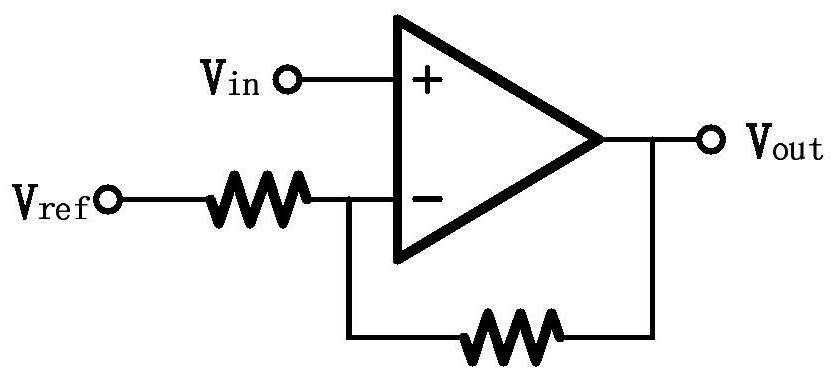
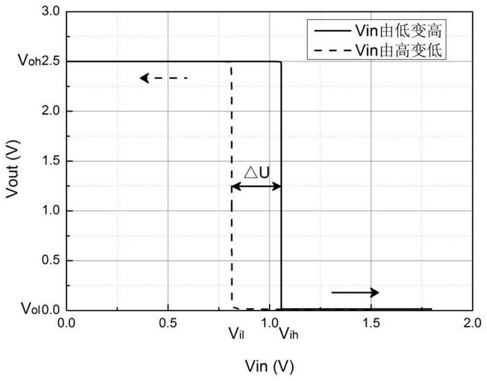
technical field [0001] The present application relates to the technical field of integrated circuits, in particular to a level conversion circuit. Background technique [0002] In monolithic microwave integrated circuits such as radio frequency amplifiers and radio frequency switches, level conversion circuits are used as an important part to realize logic control functions such as state switching and switch on and off. Due to the remarkable characteristics of GaAs-based pseudo-high electron mobility transistors, such as high characteristic frequency, fast switching speed, good noise performance, and high output power, the GaAs pHEMT process has become one of the mainstream monolithic microwave integrated circuit design processes. [0003] The comparison circuit is an important component unit in the level conversion circuit. The common single-limit comparison circuit is as figure 1 As shown, its sensitivity is very high, but when the input voltage fluctuates slightly near t...

Claims


Application Information

Patent Timeline
IPC IPC(8): H03K19/0185
CPCH03K19/0185
Inventor 汪宁欢李亚军郑远何旭杨磊
Owner 南京国微电子有限公司
Why Eureka
Try Eureka