A nearly equal-thickness dieless spinning method for thin-walled parts of a convex busbar revolving body

A dieless spinning, rotary body technology, applied in electrical program control, complex mathematical operations, digital control, etc., to achieve the effect of improving manufacturing flexibility, improving product forming uniformity, and solving demolding problems

Active Publication Date: 2022-07-08
SHENYANG AEROSPACE UNIVERSITY
View PDF8 Cites 0 Cited by
  • Summary
  • Abstract
  • Description
  • Claims
  • Application Information

AI Technical Summary

Problems solved by technology

[0003] Aiming at the problems existing in the prior art, the present invention provides a nearly equal-thick dieless spinning method for thin-walled parts of a convex generatrix rotating body, which adopts a spherical rotary wheel and performs spinning forming with a specific rotary wheel track, which is different from the traditional Compared with the advanced profiling mandrel spinning method, it effectively solves the problem of demoulding, and can effectively compensate for the thinning of the workpiece wall thickness caused by dieless spinning, realize the wall thickness control of dieless spinning, and effectively improve the uniformity of product forming , which can further enhance the flexibility of product manufacturing

Method used


Image

  • A nearly equal-thickness dieless spinning method for thin-walled parts of a convex busbar revolving body
  • A nearly equal-thickness dieless spinning method for thin-walled parts of a convex busbar revolving body
  • A nearly equal-thickness dieless spinning method for thin-walled parts of a convex busbar revolving body

Examples


Embodiment Construction

[0043] The present invention will be further described in detail below with reference to the accompanying drawings and specific embodiments.

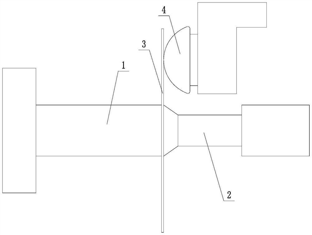
[0044] In this embodiment, the model of the CNC spinning machine is PS-CNCSXY-5, the CNC spinning machine has a built-in Siemens CNC system, the rotational speed of the main shaft 1 is set to 200 r / min; the outer diameter of the circular slab 3 is 100 mm, and the circular The plate thickness of the slab 3 is 2.05 mm, and the material of the circular slab 3 is 6061-O state aluminum alloy.

[0045] A nearly equal-thickness dieless spinning method for a thin-walled revolving body of a convex busbar, comprising the following steps:

[0046] Step 1: Select a CNC spinning machine, press the circular slab 3 figure 1 As shown, it is clamped between the main shaft 1 and the tail top 2 of the CNC spinning machine to ensure that the axial centerlines of the circular slab 3, the main shaft 1 and the tail head 2 coincide;

[0047] Step 2: Install th...


PUM


Abstract

A nearly equal-thickness dieless spinning method for a thin-walled rotary body of a convex busbar. The steps are: clamping a circular slab between a main shaft and a tail top of a CNC spinning machine to ensure that the circular slab, the main shaft and the tail The axial centerlines of the top three coincide; install a spherical roller with rounded chamfers on the radial edge on the CNC spinning machine, and the rounded chamfer and the spherical surface of the spherical roller are smoothly tangent transition; adjust the spherical roller height, so that the axial centerlines of the spherical roller, the circular slab, the main shaft and the tail top are in the same horizontal plane, and the axial centerline of the spherical roller is parallel to the axial centerline of the main shaft; cubic splines are used. The motion trajectory equation of the spherical roller is derived by the curve theory calculation method; the derived spherical roller motion trajectory equation is compiled into a numerical control code program and input into the system of the numerical control spinning machine; Spin forming process, until the circular slab is processed into a thin-walled convex busbar revolving body with a wall thickness of nearly equal thickness.

Description

technical field [0001] The invention belongs to the technical field of metal plate spinning and forming, and in particular relates to a nearly equal thickness dieless spinning method for a thin-walled part of a convex busbar revolving body. Background technique [0002] Spinning is widely used in aviation, aerospace, automobile and other industrial fields because of its high efficiency, low cost, and high material utilization. Since the advent of modern spinning technology, scholars at home and abroad have carried out a lot of research work on the spinning forming of conventional rotary parts. After continuous improvement, the theory of accurate and stable forming of circular section spinning technology has been greatly developed. In industrial production, thin-walled parts of a convex busbar with large middle and small ends are often encountered, and the workpiece of this shape has the problem of difficulty in demoulding when spinning with traditional profiling core molds. ...

Claims


Application Information

Patent Timeline
Patent Type & Authority Patents(China)
IPC IPC(8): B21D22/14G05B19/19G06F17/11G06F17/16
CPCB21D22/14G05B19/19G06F17/11G06F17/16Y02P70/10
Inventor 贾震文彦臻韩志仁包惠莉刘宝明
Owner SHENYANG AEROSPACE UNIVERSITY
Why Eureka
Try Eureka