A car stop device

A technology of blocking cars and blocking nets, which is applied to roads, buildings, and restricted traffic, etc. It can solve the problems of long deployment time of flexible car blocking devices, long braking distance, poor blocking effect, etc., and achieves shortened braking distance and small damage , long service life effect

Active Publication Date: 2022-03-01
SICHUAN JIUZHOU ELECTRIC GROUP
View PDF11 Cites 0 Cited by
  • Summary
  • Abstract
  • Description
  • Claims
  • Application Information

AI Technical Summary

Problems solved by technology

[0007] The purpose of the present invention is to provide a car-stopping device to solve the problems of long laying time, long braking distance and poor blocking effect of existing flexible car-stopping devices

Method used


Image

  • A car stop device
  • A car stop device
  • A car stop device

Examples


Embodiment 1

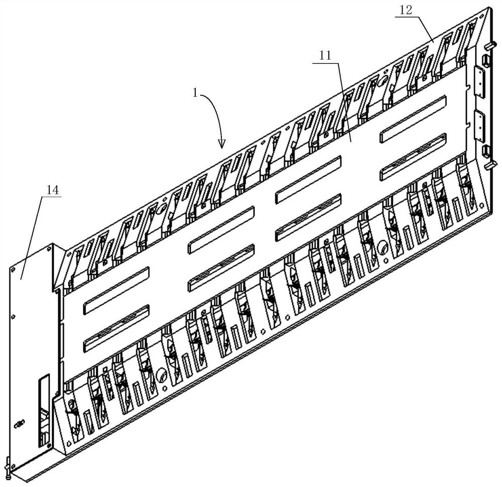
[0069] like Figure 1-Figure 13 As shown, a vehicle blocking device includes a support frame 1, a rotating mechanism 2 and a blocking net 3;

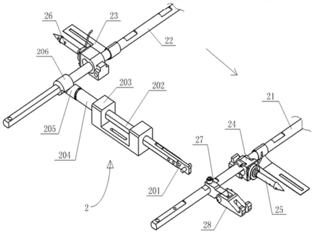
[0070] The rotating mechanism 2 is installed on the support frame 1, and the rotating mechanism 2 includes a first rotating shaft 21, a second rotating shaft 22 and a link mechanism;

[0071] The first rotating shaft 21 and the second rotating shaft 22 are installed on both sides of the support frame 1 respectively, the first rotating shaft 21 and the second rotating shaft 22 are provided with shrapnel 23, and the first rotating shaft 21 is connected with the fixing seat 24 The first air discharge nail 25 is connected, the second rotating shaft 22 is connected with the second air discharge nail 26 through the fixing seat 24, and the first air discharge nail 25 and the second air discharge nail 26 can be separated from the fixing seat under the action of external force twenty four;

[0072] When the first rotating shaft 21 rotates to t...

Embodiment 2

[0089] This embodiment is based on embodiment 1, and the difference with embodiment 1 is:

[0090] The driving mechanism includes a first motor and a second motor, and the first motor and the second motor are respectively used to drive the first rotating shaft 21 and the second rotating shaft 22 to rotate.

[0091] In this embodiment, the first rotating shaft 21 and the second rotating shaft 22 are directly driven and rotated by the first motor and the second motor, and there is no need for a link mechanism and an elastic piece 23 .

[0092] The working process of this embodiment is as follows:

[0093] When it is necessary to block the car, the first rotating shaft 21 is driven by the first motor to rotate, so that the first discharge air nail 25 is rotated to the working state and inserted into the front wheel of the car, and one end of the blocking net 3 is wound on the front wheel, and then The second rotating shaft 22 is driven by the second motor to rotate, so that the ...

Embodiment 3

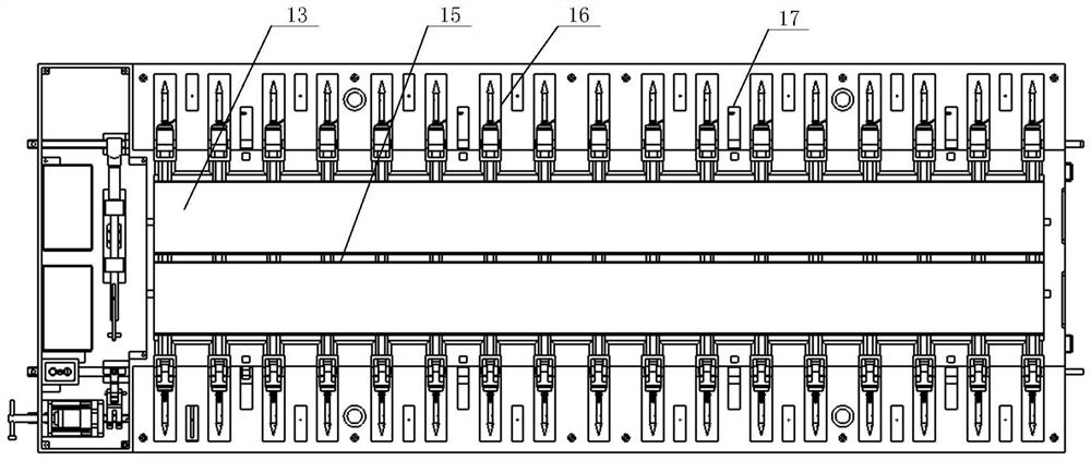
[0095] like Figure 1-Figure 13 As shown, this embodiment is based on Embodiment 1, and one end of the sliding shaft 202 is provided with a square groove, and the magnetic hanging rod 201 is installed in the square groove through bolts or screws; the hook 28 is rotatably arranged on the fixed block 27; The cavity is provided with a partition 15, the blocking net 3 is folded and placed in the cavity, the bottom plate 13 is provided with a linkage chamber 14 for installing a linkage mechanism; the guide base 203 is a U-shaped structure, the The sliding shaft 202 passes through the two side walls of the U-shaped structure.


PUM


Abstract

The invention discloses a vehicle blocking device, which includes a support frame, a rotating mechanism and a blocking net; the rotating mechanism is installed on the supporting frame, and the rotating mechanism includes a first rotating shaft, a second rotating shaft and a driving mechanism; the first The rotating shaft and the second rotating shaft are installed on both sides of the support frame respectively, the first rotating shaft is connected with the first discharge air nail through the fixing seat, the second rotating shaft is connected with the second discharging air nail through the fixing seat, and the first rotating shaft is connected with the second discharging air nail through the fixing seat. The discharge air nail and the second discharge air nail can be separated from the fixed seat under the action of external force; the driving mechanism is used to drive the first rotating shaft and the second rotating shaft to rotate, and the first discharging air nail, The second air discharge nails are inserted into the front wheel and the rear wheel of the automobile respectively; the blocking net is placed in the support frame; both ends of the blocking net are respectively connected with the first air discharge nails and the second air discharge nails. The invention solves the problems of long laying time, long braking distance and poor blocking effect of the existing flexible car blocking device.

Description

technical field [0001] The invention relates to the technical field of vehicle blocking equipment, in particular to a vehicle blocking device. Background technique [0002] Existing vehicle arresting technical equipment mainly includes: rigid arresting equipment, flexible arresting equipment, mesh nail combined arresting equipment, etc. [0003] Rigid arresting equipment mainly protects fixed environmental places, and uses its structural shape or weight to arrest intruding vehicles, including vehicle arresting piles, L-shaped arresting equipment, etc. Most of the rigid arresting equipment uses hydraulic cylinders to drive the arresting piles to rise to intercept, and the control methods include manual, electric and remote control. Although the system can achieve short-distance interception, it has two disadvantages: one is that it is easy to cause damage to the vehicle, and it poses a great threat to the life safety of the people in the vehicle. Once a mistake occurs, it wi...

Claims


Application Information

Patent Timeline
Patent Type & Authority Patents(China)
IPC IPC(8): E01F13/12
CPCE01F13/123
Inventor 朱鹏龙白竹川吴磊张庆军
Owner SICHUAN JIUZHOU ELECTRIC GROUP
Why Eureka
Try Eureka