Heat and humidity independent control system with dehumidification heat exchanger coupled with compression heat pump

A heat and humidity independent control and heat exchanger technology, which is applied in air conditioning systems, household heating, heating methods, etc., can solve the problems of reduced heat transfer capacity, heat and humidity loads that cannot be handled independently, and unstable operation, etc., to achieve heat transfer The effect of reducing loss, omitting the secondary heat exchange link in the middle, and saving regeneration load

Active Publication Date: 2021-06-15
SHANGHAI JIAO TONG UNIV
View PDF10 Cites 1 Cited by
  • Summary
  • Abstract
  • Description
  • Claims
  • Application Information

AI Technical Summary

Problems solved by technology

Due to the desiccant coating on the surface of the desiccant heat exchanger, the heat transfer capacity is significantly reduced. If the desiccant heat exchanger is used alone for temperature and humidity adjustment, a larger heat exchanger area is required, which does not meet the economic requirements, and the heat and humidity load cannot be handled independently.
At present, the way of using the heat pump coupled with the dehumidification heat exchanger is mostly to replace the traditional condenser and evaporator with a dehumidification heat exchanger, and realize the conversion of the two dehumidification heat exchangers in the dehumidification and regeneration states through the mode change of the four-way reversing valve. However, since the mode switching process of the four-way reversing valve takes a long time to balance the internal pressure of the heat pump cycle, the operation of this coupling method is not stable.

Method used


Image

  • Heat and humidity independent control system with dehumidification heat exchanger coupled with compression heat pump
  • Heat and humidity independent control system with dehumidification heat exchanger coupled with compression heat pump

Examples


Embodiment Construction

[0029] The following describes several preferred embodiments of the present invention with reference to the accompanying drawings, so as to make the technical content clearer and easier to understand. The present invention can be embodied in many different forms of embodiments, and the protection scope of the present invention is not limited to the embodiments mentioned herein.

[0030] In the drawings, components with the same structure are denoted by the same numerals, and components with similar structures or functions are denoted by similar numerals. The size and thickness of each component shown in the drawings are shown arbitrarily, and the present invention does not limit the size and thickness of each component. In order to make the illustration clearer, the thickness of parts is appropriately exaggerated in some places in the drawings.

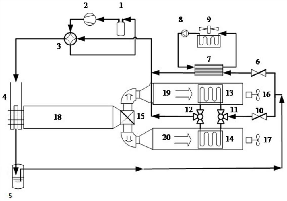
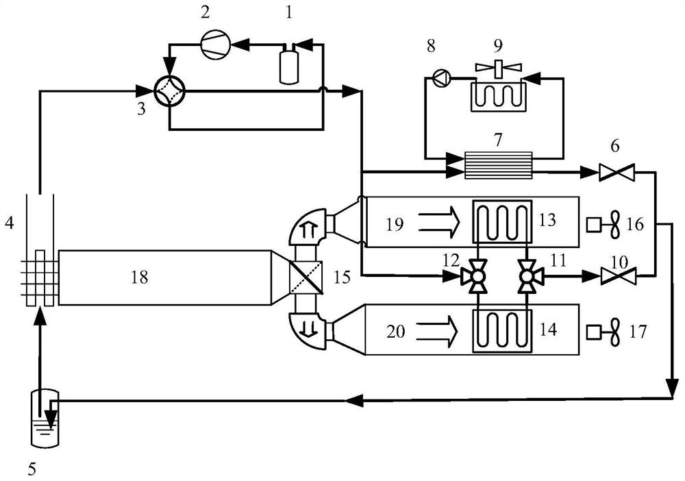
[0031] like figure 1 The heat and humidity independent control system of a dehumidification heat exchanger coupled with a compress...


PUM


Abstract

The invention discloses a heat and humidity independent control system with a dehumidification heat exchanger coupled with a compression heat pump, and relates to the technical field of heat and humidity control in air conditioning systems. The independent control system comprises a gas-liquid separator, a compressor, a fluorine path four-way valve, an outdoor heat exchanger, a liquid accumulator, a first throttle valve, a second throttle valve, a temperature module and a humidity module. The temperature module comprises an indoor heat exchanger, a chilled water pump and a fan coil. The humidity module comprises a first three-way valve, a second three-way valve, a first dehumidification heat exchanger, a second dehumidification heat exchanger, a four-way air valve, a first induced draft fan, a second induced draft fan, a first air duct, a second air duct and a third air duct. According to the independent control system, humidity control of dehumidification in summer and humidification in winter is achieved while refrigeration and heat supply are achieved; the evaporation temperature of the heat pump is increased through independent control over heat and humidity, and the energy efficiency of the system is improved.

Description

technical field [0001] The invention relates to the technical field of heat and humidity control in an air conditioning system, in particular to a heat and humidity independent control system in which a dehumidification heat exchanger is coupled with a compression heat pump. Background technique [0002] In recent years, with the promotion of urbanization and the construction of a modern society, the number of commercial buildings and civil buildings has increased simultaneously. At the same time, the improvement of living standards has also proposed high-precision, low energy consumption, and stable operation in all seasons for the temperature and humidity adjustment of artificial environments. Wait for higher requirements. [0003] At present, the commonly used refrigeration and air-conditioning systems generally use the dew point condensation method for humidity adjustment. In order to meet the dew point temperature requirements of humidity treatment, the outlet temperatu...

Claims


Application Information

Patent Timeline
Patent Type & Authority Applications(China)
IPC IPC(8): F24F3/14F24F13/30F24F11/84
CPCF24F3/14F24F13/30F24F11/84F24F2003/1446
Inventor 代彦军陈尔健赵耀柴少伟
Owner SHANGHAI JIAO TONG UNIV
Why Eureka
Try Eureka