Optical system, camera module and electronic equipment

An optical system, image-side technology, applied in the field of optical system, camera module and electronic equipment, can solve the problem of insufficient quality of photographing and imaging

Active Publication Date: 2021-06-15
JIANGXI JINGCHAO OPTICAL CO LTD
View PDF6 Cites 0 Cited by
  • Summary
  • Abstract
  • Description
  • Claims
  • Application Information

AI Technical Summary

Problems solved by technology

However, in the current market, the image quality of portable wide-angle lenses such as four-element, five-element, and six-element lenses is not good enough. In order to meet consumers’ requirements for image quality, higher-end lenses are needed to improve image quality.

Method used


Image

  • Optical system, camera module and electronic equipment
  • Optical system, camera module and electronic equipment
  • Optical system, camera module and electronic equipment

Examples


no. 1 example

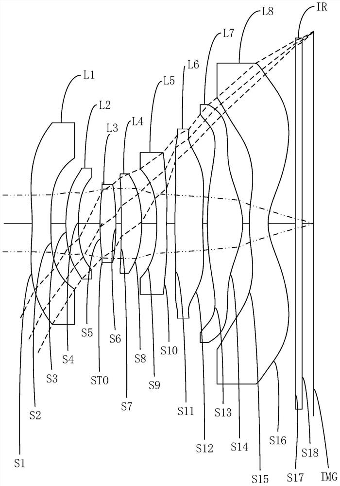
[0061] Please refer to Figure 1a with Figure 1b , the optical system of this embodiment includes a diaphragm STO and a first lens L1, a second lens L2, a third lens L3, a fourth lens L4, a fifth lens L5, and a sixth lens L6 arranged in sequence from the object side to the image side , the seventh lens L7 and the eighth lens L8. The surface shape and refractive power of the first lens L1 to the eighth lens L8 are as follows:

[0062] The first lens L1 has a negative refractive power, and both the object side S1 and the image side S2 of the first lens L1 are concave at the near optical axis;

[0063] The second lens L2 has positive refractive power, the object side S3 of the second lens L2 is convex at the near optical axis, and the image side S4 is concave at the near optical axis;

[0064] The third lens L3 has a positive refractive power, and the object side S5 and the image side S6 of the third lens L3 are both convex at the near optical axis;

[0065] The fourth lens L...

no. 2 example

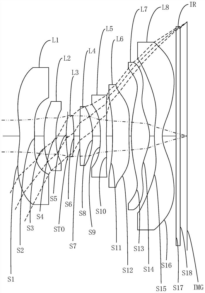
[0085] Please refer to Figure 2a with Figure 2b , the optical system of this embodiment includes a diaphragm STO and a first lens L1, a second lens L2, a third lens L3, a fourth lens L4, a fifth lens L5, and a sixth lens L6 arranged in sequence from the object side to the image side , the seventh lens L7 and the eighth lens L8. The surface shape and refractive power of the first lens L1 to the eighth lens L8 are as follows:

[0086] The first lens L1 has a negative refractive power, the object side S1 of the first lens L1 is concave at the near optical axis, and the image side S2 is convex at the near optical axis;

[0087] The second lens L2 has a negative refractive power, the object side S3 of the second lens L2 is convex at the near optical axis, and the image side S4 is concave at the near optical axis;

[0088] The third lens L3 has a positive refractive power, and the object side S5 and the image side S6 of the third lens L3 are both convex at the near optical axis...

no. 3 example

[0106] Please refer to Figure 3a with Figure 3b , the optical system of this embodiment includes a diaphragm STO and a first lens L1, a second lens L2, a third lens L3, a fourth lens L4, a fifth lens L5, and a sixth lens L6 arranged in sequence from the object side to the image side , the seventh lens L7 and the eighth lens L8. The surface shape and refractive power of the first lens L1 to the eighth lens L8 are as follows:

[0107] The first lens L1 has a negative refractive power, and both the object side S1 and the image side S2 of the first lens L1 are concave at the near optical axis;

[0108] The second lens L2 has positive refractive power, the object side S3 of the second lens L2 is convex at the near optical axis, and the image side S4 is concave at the near optical axis;

[0109] The third lens L3 has a positive refractive power, and the object side S5 and the image side S6 of the third lens L3 are both convex at the near optical axis;

[0110] The fourth lens ...


PUM


Abstract

Provided are an optical system, a camera module and electronic equipment. The optical system sequentially comprises, from an object side to an image side, a first lens element with negative refractive power which has an object-side surface being concave in a paraxial region thereof; a second lens element; a third lens element with positive refractive power which has an object-side surface and an image-side surface being convex in a paraxial region thereof; a fourth lens element with positive refractive power which has an image-side surface being convex in a paraxial region thereof; a fifth lens element with negative refractive power which has a concave object-side surface in a paraxial region thereof; a sixth lens element which has a concave image-side surface in a paraxial region thereof; a seventh lens element with positive refractive power which has an object-side surface and an image-side surface being convex in a paraxial region thereof; and an eighth lens element with negative refractive power which has an object-side surface being convex in a paraxial region thereof and an image-side surface being concave in a paraxial region thereof. By reasonably configuring the surface types and refractive power of the first to eighth lens elements, the imaging quality of the optical system is improved.

Description

technical field [0001] The invention belongs to the technical field of optical imaging, and in particular relates to an optical system, a camera module and electronic equipment. Background technique [0002] With the continuous development of photographic imaging technology, taking pictures has become an important indicator for consumers to measure the quality of electronic equipment, and large wide-angle optical lenses have become very popular. However, in the current market, the image quality of portable wide-angle lenses such as four-element, five-element, and six-element lenses is not good enough. In order to meet consumers’ requirements for image quality, higher-end lenses are needed to improve image quality. Contents of the invention [0003] The purpose of the present invention is to provide a high-level optical system, camera module and electronic equipment, which can improve the imaging quality. [0004] For realizing the purpose of the present invention, the pre...

Claims


Application Information

Patent Timeline
Patent Type & Authority Applications(China)
IPC IPC(8): G02B13/06G02B13/00G02B13/18
CPCG02B13/06G02B13/0015G02B13/0045
Inventor 杨懿邹金华李明
Owner JIANGXI JINGCHAO OPTICAL CO LTD
Why Eureka
Try Eureka