
Power transmission line allowable current-carrying capacity dynamic switching method

A technology that allows current carrying capacity and transmission line to be applied in the field of dynamic switching of allowable current carrying capacity of transmission lines. It can solve the problems of small allowable current carrying capacity, line damage, and large allowable current carrying capacity, so as to increase real-time matching degree and reduce manual work. The effect of accurate correction of volume and limit value

Pending Publication Date: 2021-06-15
STATE GRID HEBEI ELECTRIC POWER CO LTD +1
View PDF0 Cites 0 Cited by
  • Summary
  • Abstract
  • Description
  • Claims
  • Application Information

AI Technical Summary

Problems solved by technology

However, the ambient temperature in different regions and at different times changes in real time and is not the same. This fixed mode and one-size-fits-all limit switching method directly lead to a mismatch between the allowable carrying capacity of the line and the ambient temperature. Extremely high temperature weather (over 40° ) may cause the allowable carrying capacity set by the line to be too large, resulting in damage to the line
When the ambient temperature is lower than 40°, the allowable current carrying capacity set by the line will be too small, and the power supply capacity of the transmission line cannot be fully utilized, which will affect the normal power consumption of users

Method used


Image

  • Power transmission line allowable current-carrying capacity dynamic switching method
  • Power transmission line allowable current-carrying capacity dynamic switching method
  • Power transmission line allowable current-carrying capacity dynamic switching method

Examples


Embodiment Construction

[0057] The following will clearly and completely describe the technical solutions in the embodiments of the application with reference to the drawings in the embodiments of the application. Apparently, the described embodiments are only some of the embodiments of the application, not all of them. The following description of at least one exemplary embodiment is merely illustrative in nature and in no way serves as any limitation of the application, its application or uses. Based on the embodiments in this application, all other embodiments obtained by persons of ordinary skill in the art without creative efforts fall within the protection scope of this application.

[0058] It should be noted that the terminology used here is only for describing specific implementations, and is not intended to limit the exemplary implementations according to the present application. As used herein, unless the context clearly dictates otherwise, the singular is intended to include the plural, and...


PUM


Abstract

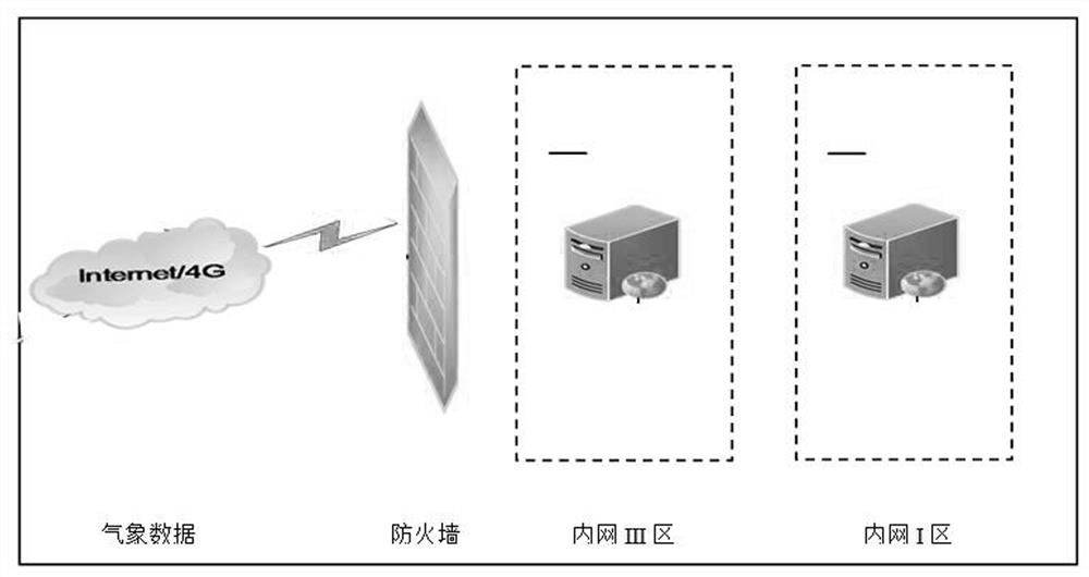
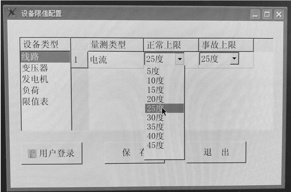
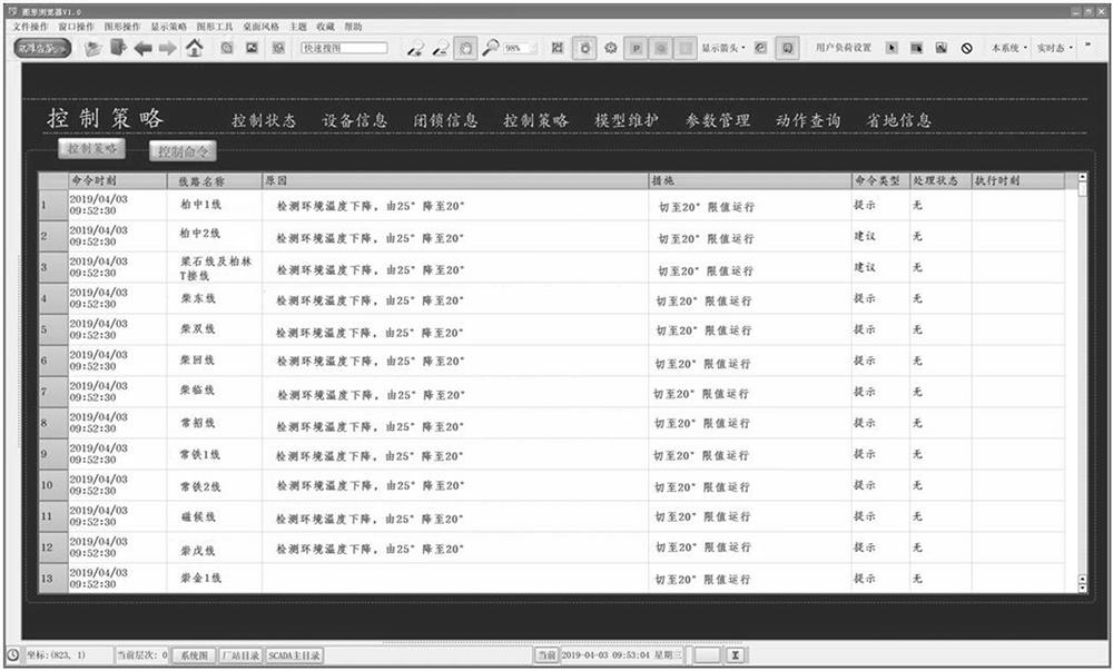
The invention discloses a power transmission line allowable current-carrying capacity dynamic switching method, which comprises the following steps of: S1, reading an environment temperature, and realizing the fusion of environment data and internal equipment limit value data on the basis of the environment temperature sensed by a D5000 system during the dynamic switching of the line allowable current-carrying capacity; S2, setting a circuit allowable current-carrying capacity switching strategy; and S3, manually setting an automatic adjustment mode or a manual intervention adjustment mode. The power transmission line allowable current-carrying capacity limit value and the environment temperature are in a matching state, the problem that a limit value is set too large or too small is avoided, the power supply capacity of the power transmission line is fully and reasonably exerted, safe and reliable permission of the power transmission line is guaranteed, and the real-time matching degree of the current-carrying capacity and the environment temperature can be further increased according to the requirement of a power grid operation mode. The D5000 system automatically and dynamically revises the allowable current-carrying capacity limit value of the power transmission line, the defects existing in a manual rigid-uniformity adjustment mode are eliminated, and the manual work amount is reduced while accurate correction of the limit value is achieved.

Description

technical field [0001] The invention relates to a method for dynamically changing the allowable carrying capacity of a transmission line, which belongs to the technical field of power grids. Background technique [0002] At present, the D5000 and other supporting systems used in the control system cannot sense the ambient temperature of the line operation, because the line carrying capacity cannot be automatically switched according to the ambient temperature, and can only be manually switched manually at a specific time period. For example, during the high temperature period in summer from June to August, the ampacity of the line is switched to the limit value of 40°C for operation, and the ampacity of the line is switched to the limit value of 25°C for the rest of the time. However, the ambient temperature in different regions and at different times changes in real time and is not the same. This fixed mode and one-size-fits-all limit switching method directly lead to a mis...

Claims


Application Information

Patent Timeline
Patent Type & Authority Applications(China)
IPC IPC(8): H02J3/00
CPCH02J3/007
Inventor 裴东锋周宝玉卜明新薛曙光郭素梅江瑞敬贾鹏洲岳海群岳海涛董宇赵鑫胡晓博孙伟斌王雷雷张艳彭堃杨超刘子涵李功铭管璇王亚奇
Owner STATE GRID HEBEI ELECTRIC POWER CO LTD
Learn More