
Die, device and method for producing amorphous alloy tube

An amorphous alloy and preparation device technology, applied in the field of materials, can solve the problems of poor forming accuracy, difficulty in preparing amorphous alloy pipes, and difficulty in preparing thick-walled or curved amorphous alloy pipes, so as to improve the ability of forming amorphous alloys Effect

Active Publication Date: 2022-07-15
HENAN ZHONGYUE AMORPHOUS NEW MATERIALS
View PDF13 Cites 0 Cited by
  • Summary
  • Abstract
  • Description
  • Claims
  • Application Information

AI Technical Summary

Problems solved by technology

[0005] The present invention provides a mold, device and method for preparing amorphous alloy pipes, aiming at solving the difficulties in preparation of amorphous alloy pipes, complex process, poor forming precision and difficulty in preparing thick-walled or curved amorphous alloy pipes question

Method used


Image

  • Die, device and method for producing amorphous alloy tube
  • Die, device and method for producing amorphous alloy tube
  • Die, device and method for producing amorphous alloy tube

Examples


Embodiment 1

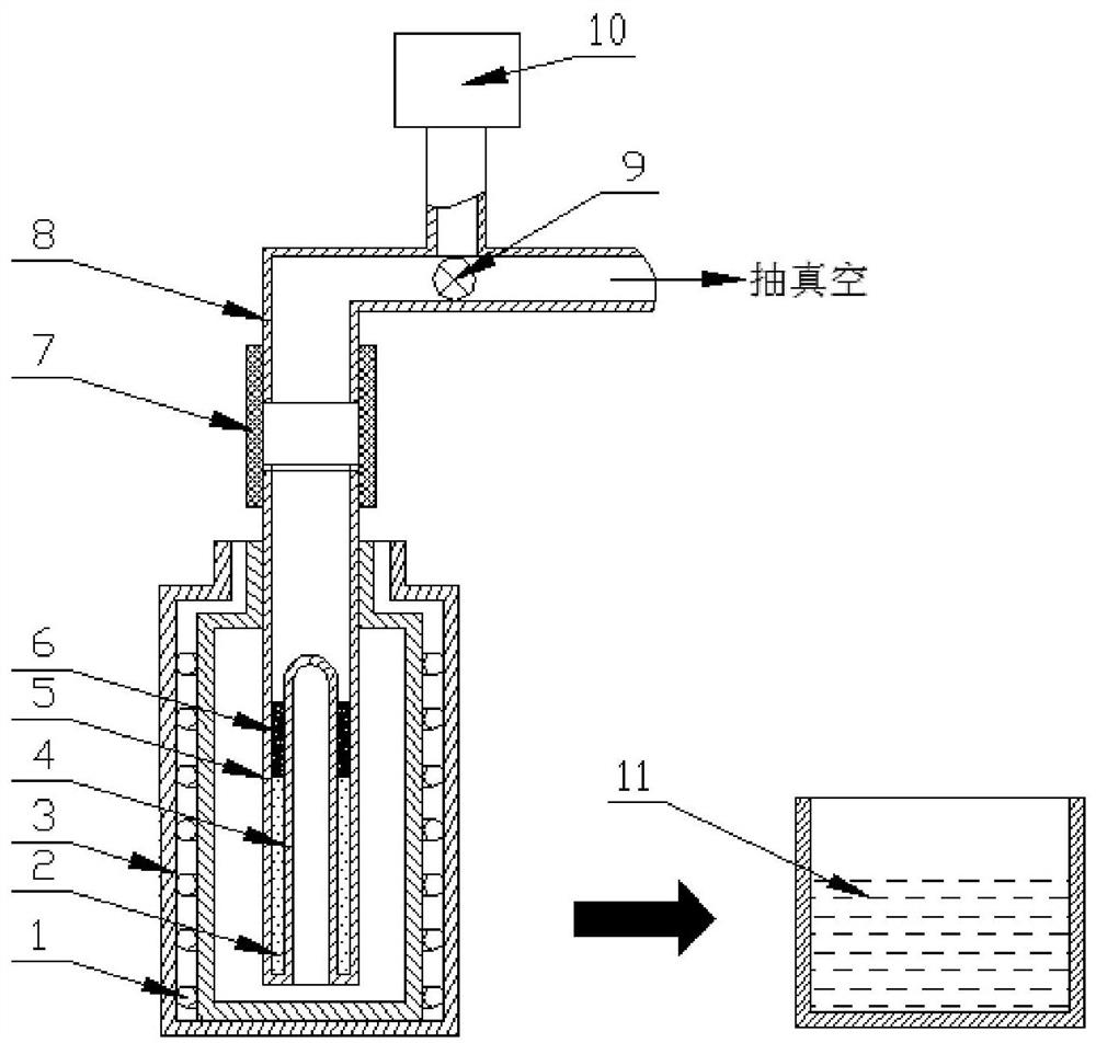
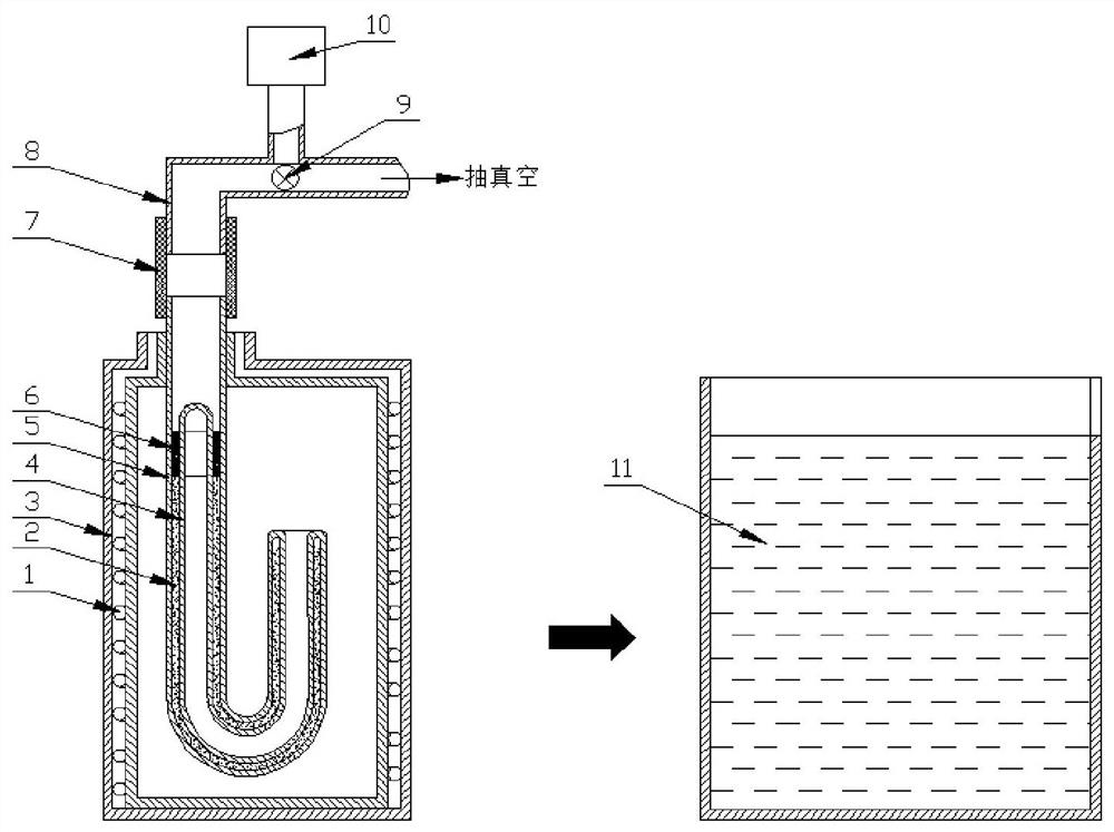
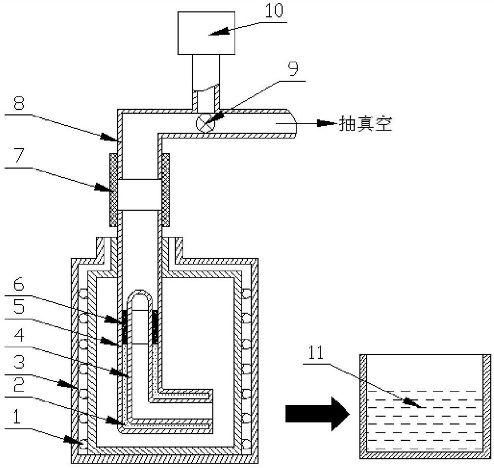
[0038] Example 1: Mold and apparatus for preparing amorphous alloy tubes.

[0039] A mold for preparing an amorphous alloy tube, see Figure 1 to Figure 3 ,include:

[0040] The outer mold quartz tube 5 and the inner mold quartz tube 4 are nested together to form the sandwich cavity, and the inner mold quartz tube 4 has an open edge corresponding to the closed end edge connected to the outer mold quartz tube 5 (that is, the inner mold quartz tube 5). The tube 4 is buckled in the outer mold quartz tube 5, and the opening of the inner mold quartz tube 4 communicates with the outside through the closed end of the outer mold quartz tube 5), and the open end of the outer mold quartz tube 5 extends to the inner mold quartz tube 5. above the closed end of the tube 4 to form a non-nested transition.

[0041] The sandwich cavity can be formed into a straight tube shape by nesting the outer mold quartz tube and the inner mold quartz tube according to the needs (such as figure 1 ), U-s...

Embodiment 2

[0046] Example 2: Preparation of Fe-based amorphous alloy tube

[0047] Based on the amorphous alloy tube preparation device described in Example 1 (see figure 1 ) to implement, including the following steps:

[0048] (1) The smelted master alloy Zr 65 Ni 10 Al 7.5 Cu 17.5 Pulverize into granules (particle size ≥ 2mm, depending on the thickness of the interlayer cavity, try to use large particles as long as it can be loaded into the interlayer cavity); take B 2 O 3 Heating at 350°C for 1 hour, then crushing and grinding to a particle size of ≥300 mesh, and then in a dry atmosphere, quickly mix with the master alloy powder in an amount of 1 / 9 of the volume of the master alloy powder.

[0049] (2) The powdery material obtained by mixing in the previous step is loaded into the interlayer cavity of the mold through the open end of the outer mold quartz tube 5;

[0050] (3) Place the mold segment corresponding to the sandwich cavity in the corresponding resistance heating f...


PUM

PropertyMeasurementUnit
thicknessaaaaaaaaaa
thicknessaaaaaaaaaa
melting pointaaaaaaaaaa

Abstract

The invention discloses a mold, device and method for preparing amorphous alloy tubes, aiming at solving the problems of difficult preparation of amorphous alloy tubes, complicated processes, poor forming precision and difficulty in forming thick-walled or curved tubes. The mold includes outer and outer mold tubes forming a sandwich cavity, the opening of the inner mold tube corresponds to the closed end of the outer mold tube, and the open end of the outer mold tube extends above the closed end of the inner mold tube to form a non-nested transition section , the mold is connected with a three-way adapter through a sealing connector to form an amorphous alloy tube preparation device, and the mold sandwich cavity is used to remelt the mother alloy and then quickly cool to form an amorphous alloy tube. The invention can prepare high-performance amorphous alloy pipes of various pipe shapes and specifications, and has the advantages of simple process, low cost and energy saving.

Description

technical field [0001] The invention relates to the technical field of materials, in particular to a mold, a device and a method for preparing an amorphous alloy tube. Background technique [0002] Amorphous alloys (also known as metallic glasses) have excellent mechanical (such as mechanics), physical (such as magnetism) and chemical (such as corrosion resistance) properties that traditional crystalline alloys cannot match, and are known as revolutionary materials. Under the close attention of people, several series of amorphous alloys have been developed. Hollow tubular amorphous alloy products are used in corrosive fluid transportation (using copper-based or iron-based amorphous alloys), magnetic cores (using iron-based soft magnetic amorphous alloys) and Coriolis mass flow meters ( Corioiis mass fiowmeter ) (using straight or U-shaped titanium-based amorphous alloy tubes) has more and more extensive application requirements; however, due to the rapid cooling rate requ...

Claims


Application Information

Patent Timeline
Patent Type & Authority Patents(China)
IPC IPC(8): B22D23/06B22D27/04B22D27/15B22D27/20C21C7/076C22C33/04C22C1/02C22C1/06
CPCB22D23/06B22D27/04B22D27/003B22D27/15B22D27/20C22C1/06C22C1/02C22C33/003C22C33/04C21C7/076C22C1/11Y02P10/20
Inventor 李福山张锁黎文强张伟伟
Owner HENAN ZHONGYUE AMORPHOUS NEW MATERIALS
Learn More