Supercharge Your Innovation With Domain-Expert AI Agents!

Oil recovery and cleaning device for CNC machine tools

A technology for cleaning devices and CNC machine tools, which is applied in the direction of metal processing machinery parts, metal processing equipment, maintenance and safety accessories, etc., and can solve problems such as inability to recycle, insufficient oil treatment, waste of oil, etc.

Active Publication Date: 2022-04-01
青岛祥银传动设备有限公司
View PDF9 Cites 0 Cited by
  • Summary
  • Abstract
  • Description
  • Claims
  • Application Information

AI Technical Summary

Problems solved by technology

[0005] In order to solve the above technical problems, the present invention provides an engine oil recovery and cleaning device for CNC machine tools to solve the problem that most of the discarded engine oil on the machine tool is directly replaced, or the engine oil is simply filtered, and the waste engine oil Often contains a variety of impurities, this treatment method will result in insufficient treatment of the oil and the waste of the oil and the problem that it cannot be recycled

Method used


Image

  • Oil recovery and cleaning device for CNC machine tools
  • Oil recovery and cleaning device for CNC machine tools
  • Oil recovery and cleaning device for CNC machine tools

Examples


Embodiment

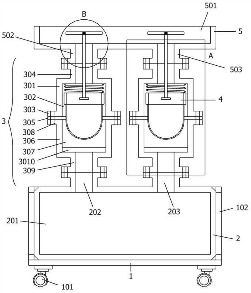
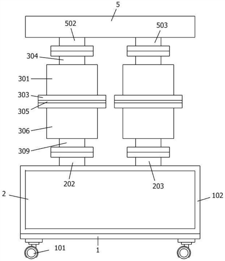
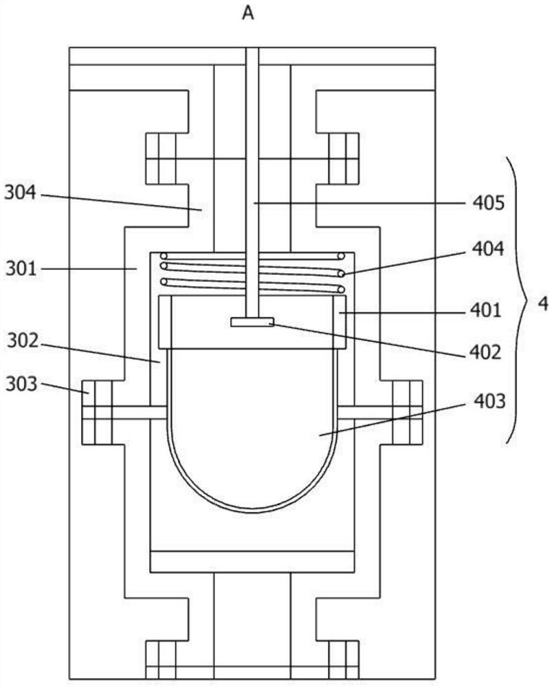
[0031] as attached figure 1 to attach Figure 6 Shown:

[0032]The invention provides an engine oil recovery and cleaning device for a numerically controlled machine tool, comprising: a bearing base plate 1, an oil recovery shell 2 is placed on the top surface of the load base plate 1, and two sets of first flanges are sealed and connected to the top of the oil recovery shell 2 Two filter residue mechanisms 3; two sets of second filter residue mechanisms 3 are fixedly installed with a set of first filter residue mechanisms 4, and the tops of the two groups of second filter residue mechanisms 3 are jointly sealed with an oil receiving housing 5; the first filter residue mechanisms 4 include Horizontal welding support plate 402, support column 405, stud 406 and circular block 407, a horizontal welding support plate 402 is welded on the inner peripheral surface of the reciprocating cylinder 401, and a support column is welded at the center of the top surface of the transverse we...


PUM


Abstract

The invention provides an oil recovery and cleaning device for a numerically controlled machine tool, which relates to the technical field of oil recovery, and solves the problem that at present, most of the discarded oil on the machine tool is directly replaced, or the oil is simply filtered, and the discarded oil is discarded. It often contains a variety of impurities. This treatment method will cause insufficient oil treatment and waste of oil, which cannot be recycled. An oil recovery and cleaning device for a numerically controlled machine tool includes a bearing bottom plate, and an organic oil recovery casing is placed on the top surface of the bearing bottom plate. When more and more waste debris is filtered and blocked in the filter screen, the bottom end face of the circular stopper is in contact with the bottom face of the inner end of the oil receiving chamber, thereby blocking the left oil receiving flange pipe B that communicates with the oil receiving chamber. Or the open end of the oil flange pipe B on the right side, so as to prevent the waste oil from flowing into the second residue filter mechanism connected with it, and avoid the accumulation of too much waste debris affecting the penetration efficiency of the waste oil.

Description

technical field [0001] The invention belongs to the technical field of engine oil recovery, and more specifically relates to an engine oil recovery and cleaning device for a numerically controlled machine tool. Background technique [0002] The machine tool needs to be lubricated with oil during use, so as to reduce the wear and heat conduction of the machine during operation. The oil in the machine tool needs to be replaced after a period of use. [0003] For example, application number: CN202010003505.9 The invention discloses a machine tool waste engine oil recovery equipment, including a casing, a heating chamber is provided at the upper end of the casing, a transmission chamber is provided at the right end of the casing, and the transmission chamber There is a transmission mechanism that provides power for the device. The heating chamber is equipped with a stirring mechanism that melts the waste engine oil. The lower end of the casing is also equipped with an impurity r...

Claims


Application Information

Patent Timeline
Patent Type & Authority Patents(China)
IPC IPC(8): B23Q11/12
CPCB23Q11/121B23Q11/122
Inventor 张雪文
Owner 青岛祥银传动设备有限公司
Features
  • R&D
  • Intellectual Property
  • Life Sciences
  • Materials
  • Tech Scout
  • Unparalleled Data Quality
  • Higher Quality Content
  • 60% Fewer Hallucinations
Learn More