
An optical fiber drawing coating device

A coating device and wire drawing technology, which is applied in the field of optical fiber wire drawing coating, can solve the problems of energy waste, inability to use bare fiber heat, and increase production costs, etc., and achieve the effects of improving the removal effect, improving the coating effect, and reducing waste

Active Publication Date: 2021-11-05
上海先权光纤科技有限公司
View PDF9 Cites 0 Cited by
  • Summary
  • Abstract
  • Description
  • Claims
  • Application Information

AI Technical Summary

Problems solved by technology

[0006] The traditional coating heating method cannot utilize the heat from the bare fiber, resulting in waste of energy and increase in production costs

Method used


Image

  • An optical fiber drawing coating device
  • An optical fiber drawing coating device
  • An optical fiber drawing coating device

Examples


Embodiment Construction

[0032] The following will clearly and completely describe the technical solutions in the embodiments of the present invention with reference to the accompanying drawings in the embodiments of the present invention. Obviously, the described embodiments are only some, not all, embodiments of the present invention. Based on the embodiments of the present invention, all other embodiments obtained by persons of ordinary skill in the art without making creative efforts belong to the protection scope of the present invention.

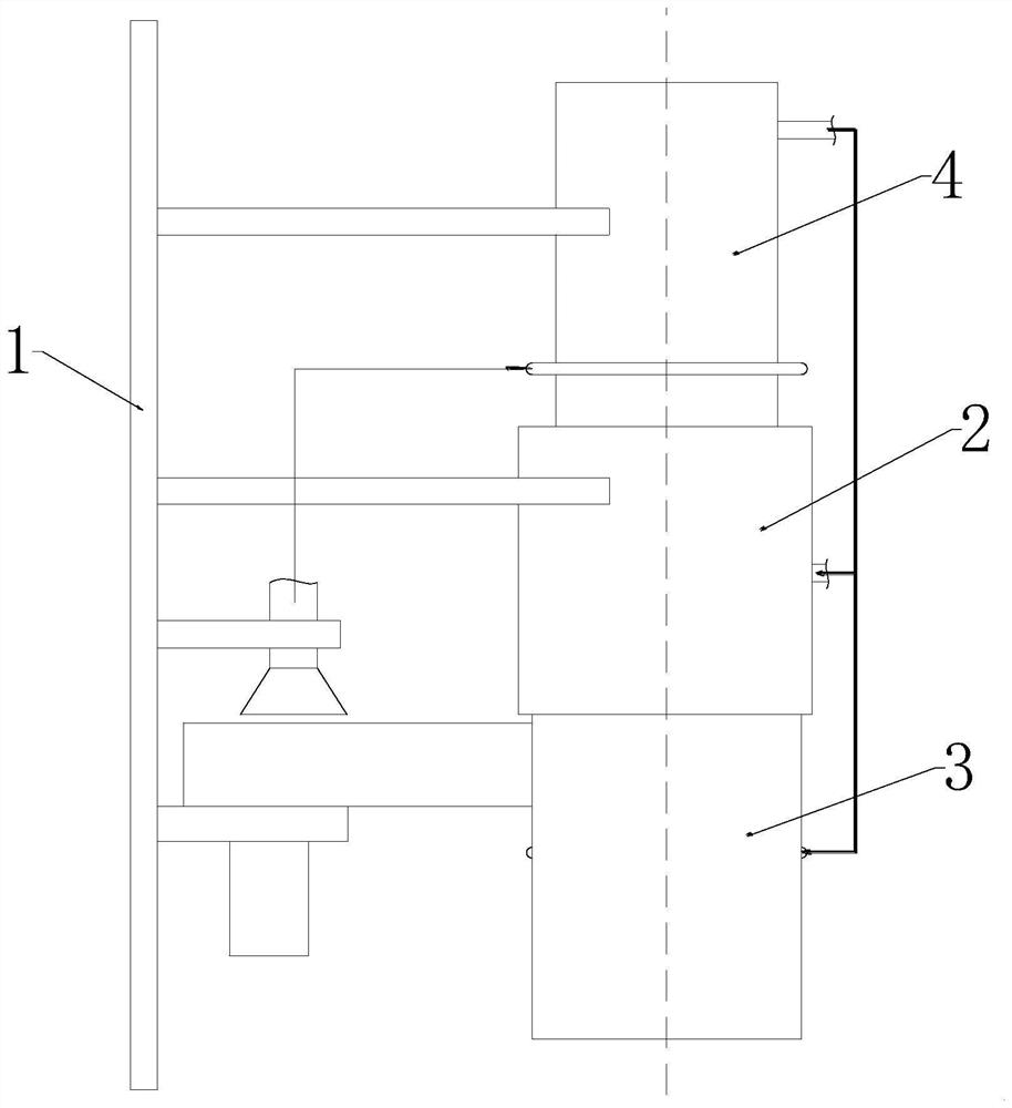
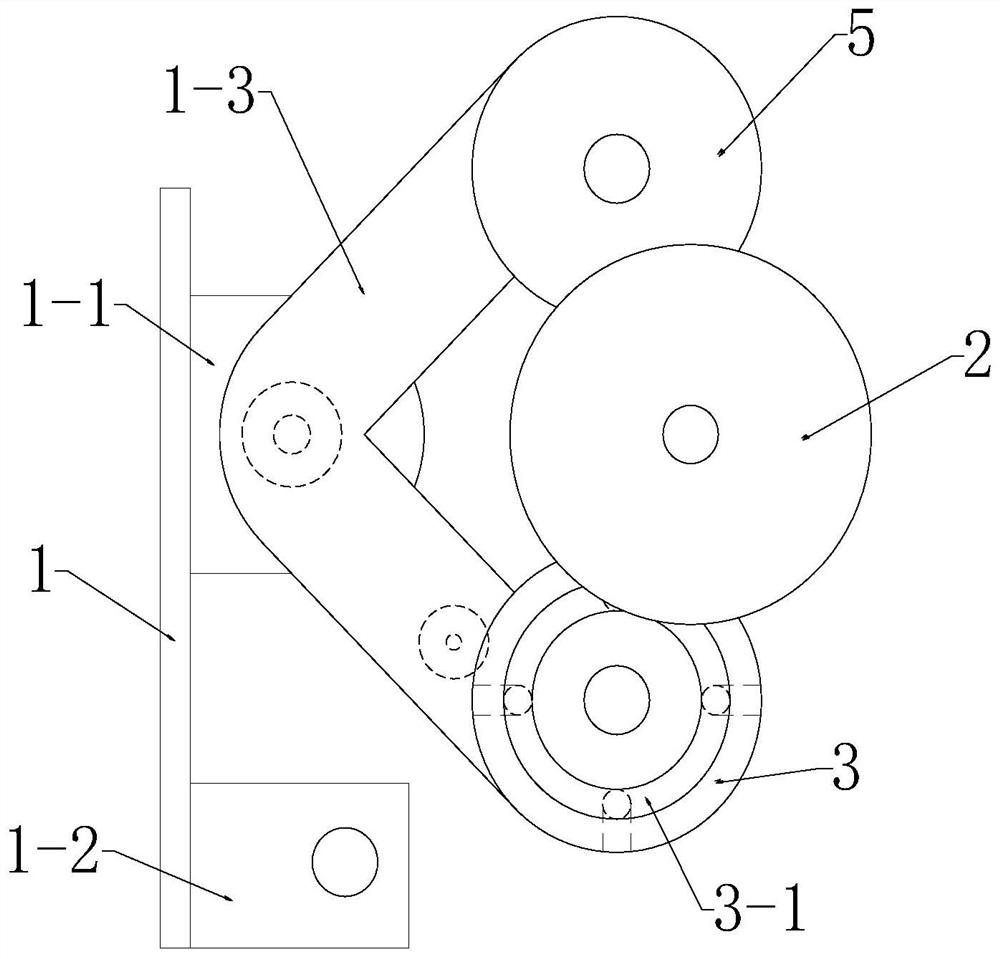
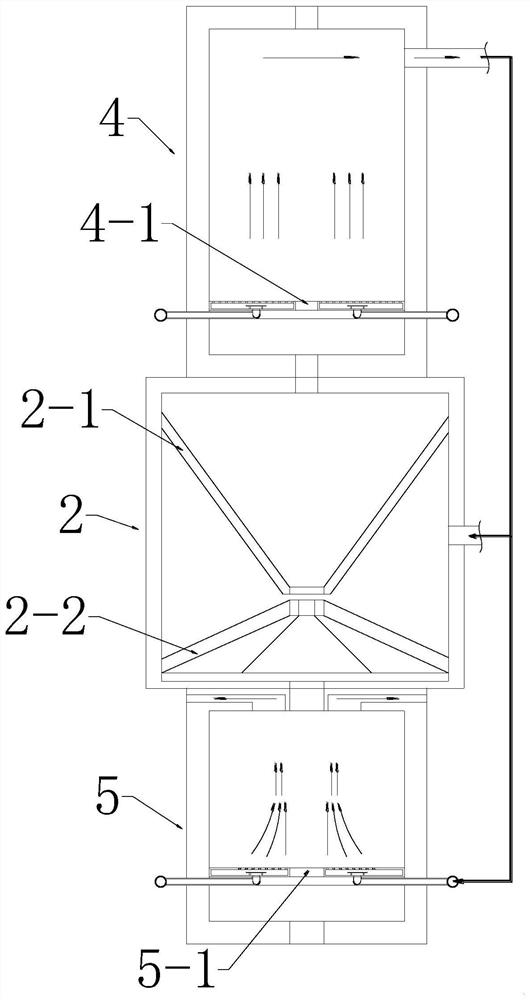
[0033] see Figure 1-8 , the present invention provides a technical solution: an optical fiber drawing coating device, the drawing coating device includes a mounting plate 1, a coating mechanism 2, a bubble treatment mechanism 3, a cooling mechanism 4, a curing mechanism 5, the mounting plate 1 from top to A cooling mechanism 4, a coating mechanism 2, a bubble treatment mechanism 3 and a solidification mechanism 5 are installed below, the bubble treatment mech...


PUM


Abstract

The invention discloses an optical fiber drawing coating device, which comprises a mounting plate, a coating mechanism, a bubble treatment mechanism, a cooling mechanism, and a curing mechanism. The mounting plate is provided with a cooling mechanism, a coating Covering mechanism, bubble processing mechanism and curing mechanism, the bubble processing mechanism and curing mechanism are located on the same horizontal plane, the bubble processing mechanism performs gas removal treatment on the paint containing bubbles, and the upper end of the cooling mechanism is connected to the lower end of the wire drawing furnace. The coating mechanism coats the bare fiber with paint and recycles the excess paint. The air bubble treatment mechanism makes the paint be thrown out of the drum through centrifugal force, and the paint is divided into multiple parts during the movement process, so that The paint hits the inner wall of the negative pressure box with the smallest volume, so that the air bubbles in the paint are broken, and the air bubbles in the paint are removed.

Description

technical field [0001] The invention relates to the technical field of optical fiber drawing and coating, in particular to an optical fiber drawing and coating device. Background technique [0002] In the process of optical fiber drawing, in order to protect the surface of the glass optical fiber, it is necessary to coat the surface of the optical fiber with multi-layer coating, which is usually done by coating the optical fiber coating. The optical fiber coating is usually made of polymer resin compound material, which is liquid at room temperature. [0003] During the coating process, if there are bubbles in the coating, it will have an impact on the quality of the optical fiber surface. Therefore, the coating device must remove the coating with bubbles before the optical fiber is produced. At present, it is basically manual operation to remove the coating at the front end of the coating device until there are no air bubbles. Moreover, the removed coatings cannot be recyc...

Claims


Application Information

Patent Timeline
Patent Type & Authority Patents(China)
IPC IPC(8): C03C25/12C03C25/26C03C25/105
CPCC03C25/105C03C25/12C03C25/26
Inventor 沈亚汝郑超
Owner 上海先权光纤科技有限公司
Learn More