
Ballast raking device and long steel rail vehicle set

A component and ballast technology, which is applied in the field of ballast removal device and long rail car group, can solve the problems of low operation efficiency, endangering driving safety, and long time consumption, so as to reduce labor costs, avoid damage to devices, and improve efficiency and safety performance Effect

Pending Publication Date: 2021-06-18
CRRC SHENYANG CO LTD
View PDF0 Cites 0 Cited by
  • Summary
  • Abstract
  • Description
  • Claims
  • Application Information

AI Technical Summary

Problems solved by technology

[0004] However, the above-mentioned devices need to be installed and disassembled manually during the operation process, which takes a long time and the operation efficiency is low
Moreover, when there are heavy obstacles such as waste rails buried in the ballast, hidden obstacles cannot be identified in advance, and collisions will occur when encountering operations, which will damage the operating devices and even endanger driving safety.

Method used


Image

  • Ballast raking device and long steel rail vehicle set
  • Ballast raking device and long steel rail vehicle set
  • Ballast raking device and long steel rail vehicle set

Examples


Embodiment 1

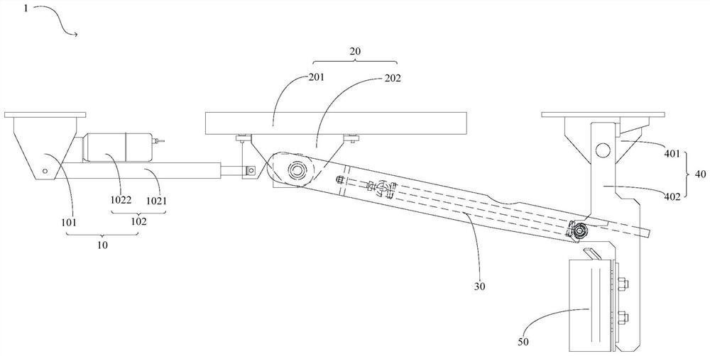
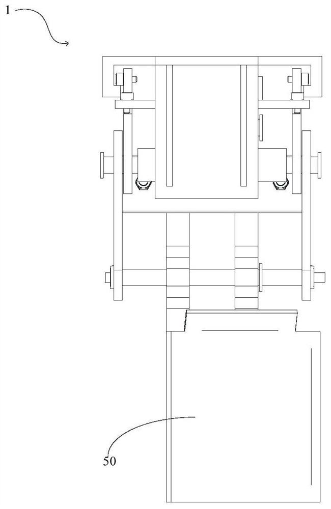
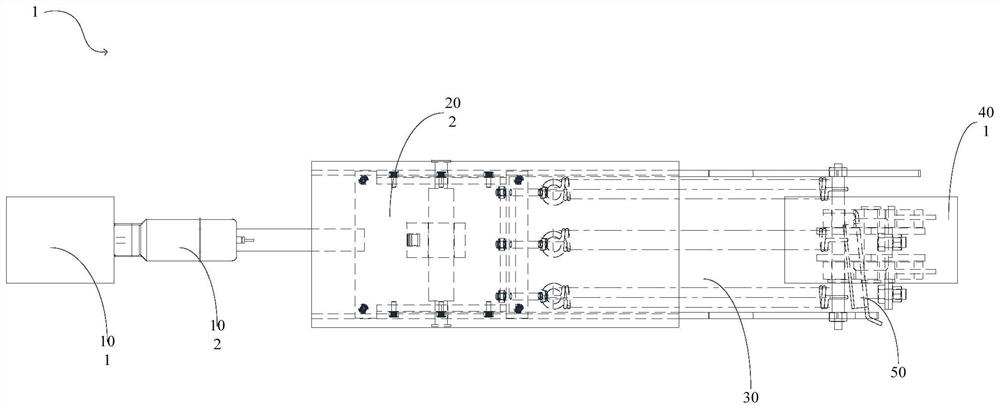
[0123] figure 1 It is a structural schematic diagram of the ballasting device provided in Embodiment 1 of the present invention. figure 2 It is the left side view of the ballasting device provided by Embodiment 1 of the present invention. image 3 It is a top view of the ballasting device provided in Embodiment 1 of the present invention. Figure 4 It is a front view of the push rod seat of the push rod assembly of the ballast removal device provided in Embodiment 1 of the present invention. Figure 5 It is a left view of the push rod seat of the push rod assembly of the ballast removal device provided in Embodiment 1 of the present invention. Figure 6 It is a structural schematic diagram of the moving assembly of the ballasting device provided in Embodiment 1 of the present invention. Figure 7 It is a front view of the chute of the support platform of the moving assembly of the ballasting device provided in Embodiment 1 of the present invention. Figure 8 It is a left ...

Embodiment 2

[0158] Figure 26 It is a schematic structural diagram of the long rail car set provided by Embodiment 2 of the present invention.

[0159] On the basis of the first embodiment above, the second embodiment of the present invention also provides a long rail car set 100, such as Figure 26 As shown, the long rail car set 100 includes a vehicle body 2 and the ballasting device 1 in the first embodiment above.

[0160] Wherein, both sides of the vehicle body 2 are respectively provided with a ballast removal device 1, and the ballast removal device 1 is fixedly connected to the side beams 21 on both sides of the vehicle body 2, specifically, the push rod seat 101, the support platform 201, the pivot arm The seat 401 is welded and fixed on the side beam 21 . Two ballast removal devices 1 are arranged symmetrically along the centerline of the vehicle body 2, and simultaneously level the ballast on the outer sides of the tracks on both sides.

[0161] It should be noted that a loc...


PUM


Abstract

The invention provides a ballast raking device and a long steel rail vehicle set. The ballast raking device comprises a push rod assembly, a moving assembly, a linkage assembly, a rotating arm assembly and an execution assembly which are sequentially connected; the push rod assembly comprises a push rod base and a push rod hinged to the push rod base; the moving assembly comprises a supporting table and a sliding part, the sliding part is hinged to the push rod, and one end of the sliding part is movably connected to the supporting table; the linkage assembly comprises a connecting frame and an elastic part, the connecting frame is hinged to the other end of the sliding part, and one end of the elastic part is fixedly arranged on the connecting frame; the rotating arm assembly comprises a rotating arm support and a rotating arm hinged to the rotating arm support, the middle of the rotating arm is connected with the other end of the elastic part, and the end, away from the rotating arm support, of the rotating arm is connected with the execution assembly; and a check block is further fixedly arranged on the rotating arm support and used for limiting the rotating range of the rotating arm. According to the invention, the ballast can be continuously and automatically pushed open without stopping, meanwhile, the labor cost can be reduced, and the operation efficiency and safety are improved.

Description

technical field [0001] The invention relates to the technical field of vehicles, in particular to a ballast removal device and a long rail car set. Background technique [0002] The long rail car group is a special car group for transporting welded long rails, which is composed of a variety of special vehicles with different functions and structures. In the construction of seamless railway lines, the long rail car group is responsible for the long rail Tasks of loading, transporting, unloading and recycling old rails. For example, the long rail car unit has the function of unloading the transported rails to both sides of the line. In order to store the unloaded rails on both sides of the line smoothly and ensure that the rail surface of the unloaded rails is not higher than the rail surface of the line, it must Level the protruding ballast on both sides of the line. That is to say, in order to make the rails have a stable and safe storage space, it is necessary to dig out ...

Claims


Application Information

Patent Timeline
IPC IPC(8): E01B27/02
CPCE01B27/026
Inventor 冯玉华盛曼曼郎宇
Owner CRRC SHENYANG CO LTD
Learn More