
Steel structure suspended ceiling reverse supporting structure

A supporting structure and steel structure technology, applied in the direction of ceiling, building components, building structure, etc., can solve the problems of increasing roof load, reducing the overall reliability of steel structure, increasing load, etc., to eliminate safety hazards, and the assembly method is simple and fast Effect

Pending Publication Date: 2021-06-18
CHINA MCC5 GROUP CORP
View PDF0 Cites 0 Cited by
  • Summary
  • Abstract
  • Description
  • Claims
  • Application Information

AI Technical Summary

Problems solved by technology

In a large-span, high-story building built with steel structures, a large number of equipment and pipelines need to be laid on the ceiling. If the traditional method of setting the steel beam transfer layer for the ceiling is adopted, the load on the roof will be greatly increased, which will not only increase the construction cost. , which also increases the difficulty of construction. If welding is used for construction, there is a risk of welding slag falling, hurting people, and causing fire, and it is difficult to ensure the structural safety of the large-span ceiling structure connected by welding.
[0003] Therefore, there is still room for improvement in the transfer layer of the existing steel structure ceiling, mainly because the transfer layer of the steel structure ceiling increases the load, which reduces the overall reliability of the steel structure; the current transfer layer welding construction still has potential safety hazards

Method used


Image

  • Steel structure suspended ceiling reverse supporting structure
  • Steel structure suspended ceiling reverse supporting structure
  • Steel structure suspended ceiling reverse supporting structure

Examples


Embodiment 1

[0029] In view of the fact that the existing steel structure has a large load, difficult construction, and many safety hazards in setting the suspended ceiling, this embodiment proposes a support structure suitable for the construction of the steel structure suspended ceiling, which can quickly and conveniently install the suspended ceiling components into the steel structure.

[0030] Specifically, the technical solution adopted in this embodiment is as follows:

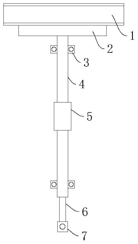
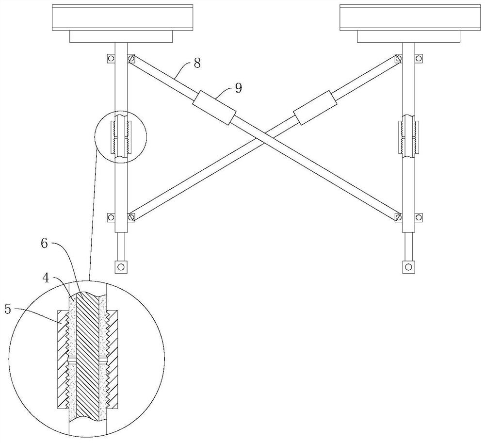
[0031] Such as figure 1 , figure 2 As shown, a steel structure suspended ceiling reverse support structure includes several support units, and the adjacent support units are connected by tensioning and fixing structures; the support units include embedded plates 2 connected with steel structure beams 1, and The lower surface of the buried plate 2 is vertically provided with hanging ribs 6 for connecting and setting the ceiling assembly. The hanging ribs 6 are provided with several sections of sleeves 4, and a usef...

Embodiment 2

[0045] This embodiment is optimized on the basis of embodiment 1, and discloses a steel structure suspended ceiling reverse support structure. The difference from embodiment 1 is that this embodiment optimizes the structure of the first adjusting member.

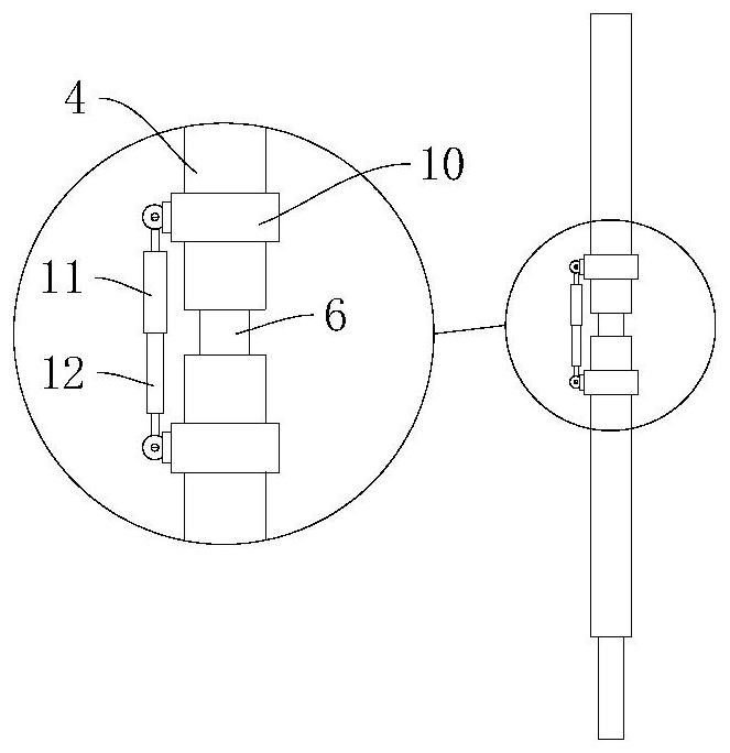
[0046] Specifically, such as image 3 As shown, in this embodiment, the end of the sleeve 4 is provided with a connecting portion 10, and the first adjusting part 5 includes a female part 11 and a sub-part 12 connected by a threaded structure, and the female part 11 is connected to the upper end The connecting portion 10 of the sleeve 4 , the sub-section is connected to the connecting portion 10 of the lower end sleeve 4 . When adopting such a scheme, the said parent part 11 and the child part 12 are relatively rotated to adjust the relative distance to realize expansion and contraction. When stretching, the mother part 11 pushes against the sleeve 4 at the upper end, and the child part 12 pushes against the sleeve 4 at the ...

Embodiment 3

[0049] This embodiment is optimized on the basis of embodiment 1, and discloses a steel structure suspended ceiling reverse support structure. The difference from embodiment 1 is that this embodiment optimizes the structure of the second adjusting member.

[0050] Specifically, such as Figure 4 As shown, in this embodiment, the end of the oblique rib casing 8 is provided with a connecting portion 10, and the second adjusting member 9 includes a female member 11 and a child member 12 connected by a threaded structure, the female member 11 and the The connecting portion 10 of the upper end of the oblique rib sleeve 8 is connected, and the sub-component 12 is connected with the connecting portion 10 of the lower end of the oblique rib sleeve 8 . When such a solution is adopted, the parent part 11 and the child part 12 are relatively close to or relatively far away from each other, thereby resisting the corresponding upper end oblique rib sleeve 8 and the lower end oblique rib sl...


PUM


Abstract

The invention relates to the technical field of steel structure construction, in particular to a steel structure suspended ceiling reverse supporting structure. The steel structure suspended ceiling reverse supporting structure comprises a plurality of supporting units, and every two adjacent supporting units are connected through a tensioning and fixing structure. Each supporting unit comprises a pre-embedded plate connected with a steel structure beam, hanging bars used for being connected with a suspended ceiling assembly are vertically arranged on the lower surfaces of the pre-embedded plates, a plurality of sections of sleeves sleeve the hanging bars, and a first adjusting piece used for adjusting the distance between the sleeves is arranged between the adjacent sleeves on the same hanging bar; and the sleeves on the different hanging bars are connected and fastened through inclined strut structures. The suspended ceiling assembly of the steel structure is connected and fixed through the hanging bars and the sleeve structures on the hanging bars, connection and installation of the suspended ceiling assembly are achieved on the premise that the load of the steel structure is not increased too much, in the actual construction process, the assembling mode is simple and rapid, welding and other operations are not needed, and potential safety hazards are eliminated.

Description

technical field [0001] The invention relates to the technical field of steel structure construction, in particular to a steel structure suspended ceiling reverse support structure. Background technique [0002] In the construction of construction, decoration and other projects, steel structural parts are generally used to form various required structures. Steel structural parts are widely used because of their high structural strength, simple and efficient construction process. In a large-span, high-story building built with steel structures, a large number of equipment and pipelines need to be laid on the ceiling. If the traditional method of setting the steel beam transfer layer for the ceiling is adopted, the load on the roof will be greatly increased, which will not only increase the construction cost. , It also increases the difficulty of construction. If welding is used for construction, there is a risk of welding slag falling, hurting people, and causing a fire, and ...

Claims


Application Information

Patent Timeline
Patent Type & Authority Applications(China)
IPC IPC(8): E04B9/00E04B9/06E04B9/20
CPCE04B9/00E04B9/06E04B9/20
Inventor 朱常睿
Owner CHINA MCC5 GROUP CORP
Learn More