
Steel frame connecting device for fabricated building auxiliary construction

A connecting device and assembled technology, which is applied in the direction of construction, building structure, stairs, etc., can solve the problems of difficult to control the vibration of stairs, increase the risk of construction, and the collision between the end of the stairs and the laminated board, so as to improve safety. Effect

Active Publication Date: 2021-06-18
中建七局第一建筑有限公司
View PDF6 Cites 2 Cited by
  • Summary
  • Abstract
  • Description
  • Claims
  • Application Information

AI Technical Summary

Problems solved by technology

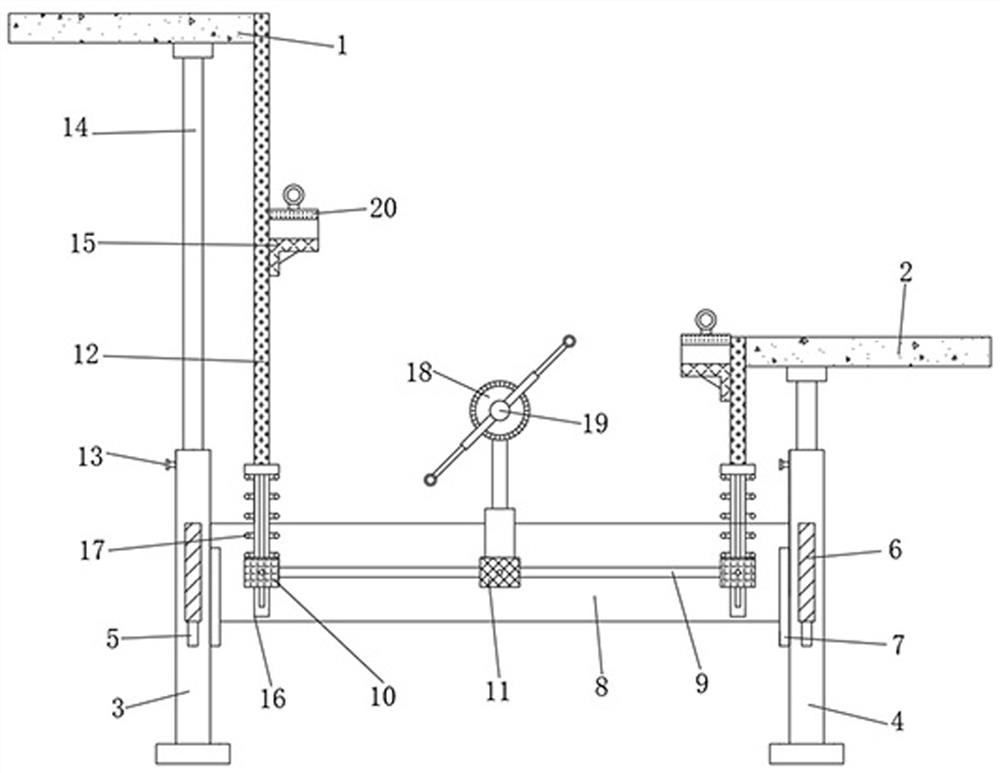
[0003] The traditional top-down hoisting staircase needs to hoist the heavy concreted stairs to a higher position, which not only increases the risk of construction, but also makes it difficult to control the vibration generated during the hoisting of the stairs, which is easy to cause breakage, and for During the construction of the stairs inside the home, due to the limited space, it is difficult to achieve top-down hoisting, and only the bottom-up hoisting method can be used. However, this hoisting method has higher requirements for the inclination angle of the stairs, which is likely to cause the end of the stairs to be out of alignment. Collision between the laminated plates, at the same time, it is necessary to control the shaking angle of the stairs when suspended in the air to ensure that the stairs rise vertically
[0004] To this end, a steel frame connection device for auxiliary construction of prefabricated buildings is provided to solve the problem of angle control and shaking range when the stairs are hoisted from bottom to top

Method used


Image

  • Steel frame connecting device for fabricated building auxiliary construction
  • Steel frame connecting device for fabricated building auxiliary construction
  • Steel frame connecting device for fabricated building auxiliary construction

Examples


Embodiment Construction

[0024] The following will clearly and completely describe the technical solutions in the embodiments of the present invention with reference to the accompanying drawings in the embodiments of the present invention. Obviously, the described embodiments are only some of the embodiments of the present invention, not all of them. Based on the embodiments of the present invention, all other embodiments obtained by persons of ordinary skill in the art without making creative efforts belong to the protection scope of the present invention.

[0025] see Figure 1 to Figure 4 , the present invention provides a technical solution:

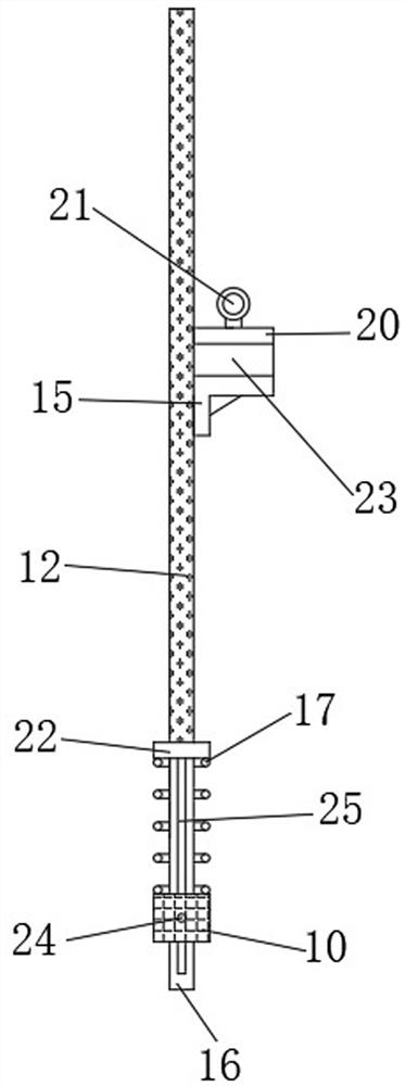
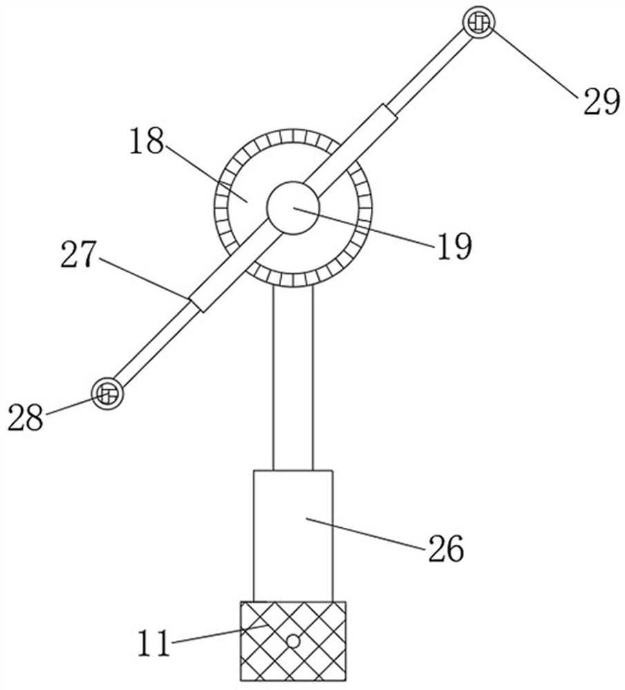
[0026] A steel frame connection device for auxiliary construction of a prefabricated building, comprising an upper laminated plate 1 and a lower laminated plate 2, a gap is left between the upper laminated plate 1 and the lower laminated plate 2, the upper laminated plate 1 and the lower laminated plate 2 The lower end is respectively provided with a group ...


PUM


Abstract

The invention relates to the technical field of building construction, in particular to a steel frame connecting device for fabricated building auxiliary construction. The steel frame connecting device comprises an upper laminated plate and a lower laminated plate, a gap is reserved between the upper laminated plate and the lower laminated plate, a group of first bases and second bases are correspondingly arranged at the lower ends of the upper laminated plate and the lower laminated plate, and the first bases and the second bases are symmetrical front and back. The steel frame connecting device for the fabricated building auxiliary construction has the beneficial effects that the distance between the left side and the right side of a staircase is limited through cooperation of a distance measuring cross beam and a limiting baffle, and the end part of the staircase is prevented from colliding with the laminated plates; and meanwhile, the inclination angle of the staircase is accurately adjusted through cooperation of a dial and a measuring rod, and the angle of the staircase during vertical hoisting can smoothly penetrate through the gaps between the laminated plates which are vertically distributed at intervals, so that the mounting safety of the staircase is improved.

Description

technical field [0001] The invention relates to the technical field of building construction, in particular to a steel frame connecting device for auxiliary construction of an assembled building. Background technique [0002] In the process of prefabricated installation and construction of stairs, the stairs need to be hoisted between a pair of laminated plates that are spaced up and down. The traditional hoisting methods mostly hoist the stairs to a high place and assemble and install from top to bottom. [0003] The traditional top-down hoisting staircase needs to hoist the heavy concreted stairs to a higher position, which not only increases the risk of construction, but also makes it difficult to control the vibration generated during the hoisting of the stairs, which is easy to cause breakage, and for During the construction of the stairs inside the home, due to the limited space, it is difficult to achieve top-down hoisting, and only the bottom-up hoisting method can b...

Claims


Application Information

Patent Timeline
Patent Type & Authority Applications(China)
IPC IPC(8): E04F11/02E04F21/26
CPCE04F11/02E04F21/26
Inventor 张晓东崔岩赵松陈斌李德鹏冯立扬
Owner 中建七局第一建筑有限公司
Learn More