Engineering machinery heat dissipation system, electronic fan control method and engineering machinery
A technology of electronic fan and heat dissipation system, applied in the direction of mechanical equipment, machine/engine, coolant flow control, etc.
- Summary
- Abstract
- Description
- Claims
- Application Information
AI Technical Summary
Problems solved by technology
Method used
Image

Examples
Embodiment Construction
[0029] The specific implementation will be described below in conjunction with the accompanying drawings.
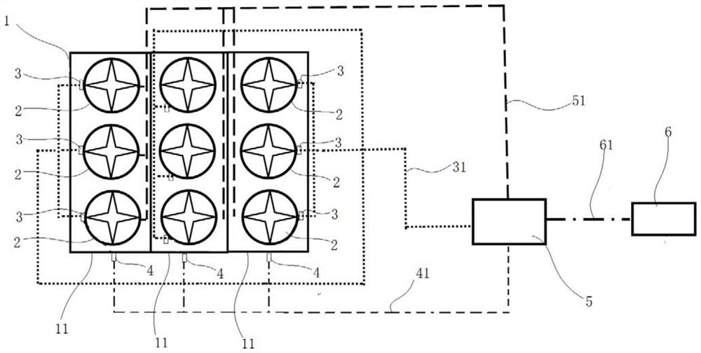
[0030] In construction machinery, the cooling system of construction machinery that uses electronic fans to drive air to dissipate heat usually includes a plurality of radiator cores, and the plurality of radiator cores are integrated and assembled together to form a radiator core assembly 1 . During the operation of construction machinery, among the radiator cores, some radiator cores have different heat dissipation requirements, and some radiator cores have the same heat dissipation requirements. Radiator cores with the same heat dissipation requirements are usually arranged overlappingly on the air duct, or Arranged next to each other. Each radiator core is equipped with at least one electronic fan, and the multiple electronic fans are divided into multiple groups, and each group of electronic fans corresponds to one radiator core or multiple radiator cores with the s...
PUM
 Abstract
Description
Claims
Application Information
PatSnap Eureka turns technology decisions into work you can execute. Powered by our Innovation Knowledge Graph, it runs expert workflows across engineering, life sciences, materials and intellectual property. Get your review-ready output in minutes.


