A rocket-based combined cycle engine with expandable air intake

A technology of air inlet and engine, which is applied in combined engines, rocket engine devices, ramjet engines, etc., can solve the problems of blocked secondary flow flow, degradation, narrow secondary flow channel, etc., to reduce the overall The effect of pressure loss

Active Publication Date: 2022-04-05
NAT UNIV OF DEFENSE TECH
View PDF8 Cites 0 Cited by
  • Summary
  • Abstract
  • Description
  • Claims
  • Application Information

AI Technical Summary

Problems solved by technology

In order to ensure sufficient power for the aircraft, the size of the ejector rocket is relatively large, accounting for more than 40% of the total cross-sectional area of ​​the flow channel, which makes the secondary flow channel in the isolation section relatively narrow. Due to the ejection and suction effect of the center rocket, the secondary flow can easily reach the speed of sound in the narrow flow channel, forming a blockage. At this time, the flow of the rocket is further increased, and the flow of the secondary flow cannot be increased.
[0003] In addition, when the center rocket performs afterburner operation, the rocket plume flow rate and total pressure increase, and the secondary flow rate cannot be increased, the rocket plume in the mixing section will further squeeze the secondary flow channel, or even completely Blocking the flow of the secondary flow, because the flow of the secondary flow is suppressed, at this time, the RBCC engine will not be able to organize the secondary injection combustion of the fuel at the rear, and the whole actually degenerates into a rocket engine
[0004] In the prior art, in order to solve the problem of secondary flow congestion in the isolation section, the isolation section is chosen to be a gradually expanding structure, but this will occupy the volume of the center rocket, which may cause problems such as insufficient thrust

Method used


Image

  • A rocket-based combined cycle engine with expandable air intake
  • A rocket-based combined cycle engine with expandable air intake
  • A rocket-based combined cycle engine with expandable air intake

Examples


Embodiment Construction

[0033] The following will clearly and completely describe the technical solutions in the embodiments of the present invention with reference to the accompanying drawings in the embodiments of the present invention. Obviously, the described embodiments are only part of the embodiments of the present invention, not all of them. Based on the embodiments of the present invention, all other embodiments obtained by persons of ordinary skill in the art without creative efforts fall within the protection scope of the present invention.

[0034] It should be noted that all directional indications (such as up, down, left, right, front, back...) in the embodiments of the present invention are only used to explain the relationship between the components in a certain posture (as shown in the accompanying drawings). Relative positional relationship, movement conditions, etc., if the specific posture changes, the directional indication also changes accordingly.

[0035] In addition, in the p...


PUM


Abstract

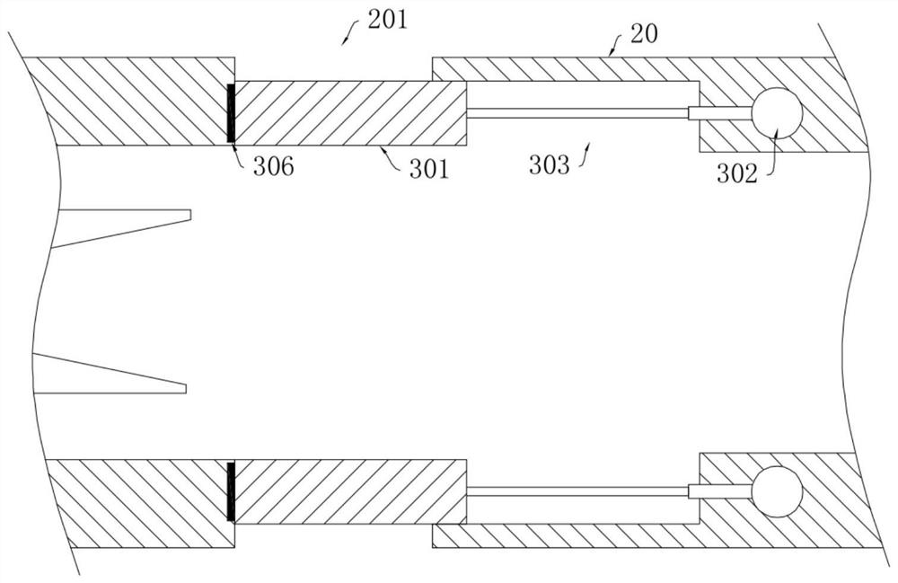
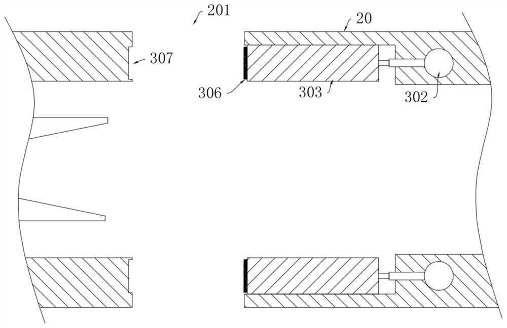
The invention discloses a rocket-based combined cycle engine with an expandable air inlet, which includes an isolation section and a mixing section connected in sequence, the isolation section is provided with a first-stage air inlet, and the mixing section is provided with a second-stage inlet near the isolation section. The air port; the primary air intake and the secondary air intake are connected in parallel on the air intake of the engine, so that the primary air intake and the secondary air intake can be opened and closed independently without interfering with each other; on the mixing section An adjustment structure is provided for adjusting the opening width of the secondary air inlet. Through the secondary air inlet, the expanded secondary air inlet can be opened in the injection mode, so that the flow rate of the injected secondary flow can be improved, and the opening size of the secondary air inlet can be adjusted by adjusting the structure, It can better control the air volume of the secondary flow; it will not occupy the space range that the center rocket should have, and the combination with the concave cavity can reduce the total pressure loss caused by the concave cavity at low speed.

Description

technical field [0001] The invention relates to the technical field of rocket-based combined cycle engines, in particular to a rocket-based combined cycle engine with an expandable air inlet. Background technique [0002] The ejection rocket is an important part of the RBCC (Rocket-Based Combined Cycle) engine, and it is the main source of engine thrust in the ejection mode (when the flight Mach number is less than 3). In order to ensure sufficient power for the aircraft, the size of the ejector rocket is relatively large, accounting for more than 40% of the total cross-sectional area of ​​the flow channel, which makes the secondary flow channel in the isolation section relatively narrow. Due to the ejection and suction effect of the center rocket, the secondary flow can easily reach the speed of sound in the narrow flow channel, forming a blockage. At this time, the flow of the rocket is further increased, and the flow of the secondary flow cannot be increased. [0003] In...

Claims


Application Information

Patent Timeline
Patent Type & Authority Patents(China)
IPC IPC(8): F02K7/18F02K1/38F02K9/97
CPCF02K7/18F02K1/38F02K1/386F02K9/97
Inventor 王泰宇王振国孙明波蔡尊杨揖心李佩波
Owner NAT UNIV OF DEFENSE TECH
Why Eureka
Try Eureka