Hydraulic motor with integral output shaft

A hydraulic motor and output shaft technology, applied in the field of hydraulic motors, can solve the problems affecting the quality and performance of hydraulic motors, thermal deformation of thin-walled ball joints, etc., and achieve the effects of simple structure, less thermal deformation, and reduced impact.

Pending Publication Date: 2021-06-18
JIANGSU ZHENJI MACHINERY MFG
9 Cites 0 Cited by

AI-Extracted Technical Summary

Problems solved by technology

[0002] In the existing technology, such as Figure 1-2 As shown, the traditional hydraulic motor generally includes a ball joint output shaft, a ball joint, a return plate, a cylinder, a plunger, a flow plate, etc.; the high-speed rotation of the motor requires the coaxiality of the ball joint, the ball joint output shaft and the cylinder body High, the concentricity deviation in the production process can easily af...

Abstract

The invention discloses a hydraulic motor with an integral output shaft. The hydraulic motor comprises a shell, the integrated output shaft, a thrust plate, a retainer plate, a plunger, a cylinder body and an end cover, wherein the integrated output shaft is sequentially equipped with a front contact section, a spherical section, a middle contact section, a synchronous section and a rear contact section from front to back in the axial direction; the front contact section is rotatably connected to the front end of the shell through a front bearing; a special-shape spring is arranged on the spherical section in a sleeving manner, and the spherical section is elastically connected with the rear surface of the retainer plate through a special-shape spring; the middle contact section is a convex ring retaining shoulder and is resisted against the front end of the cylinder body; the synchronous section is arranged in the cylinder body and is connected with the cylinder body; the rear contact section penetrates through a flow distribution plate and is rotatably connected with the end cover through a rear bearing; and a floating piston ring is arranged at the front end of the end cover, and a corrugated spring is arranged between the floating piston ring and the end cover. According to the hydraulic motor with the integral output shaft disclosed by the invention, a ball joint structure of a ball joint type output shaft is eliminated, the influence of the coaxiality on the quality and the performance of products during processing of the products can be greatly reduced, the reliability is high, the structure is simple, the hydraulic motor is mounted and maintained more conveniently.

Application Domain

Reciprocating piston engines

Technology Topic

EngineeringCylinder block +6

Image

  • Hydraulic motor with integral output shaft
  • Hydraulic motor with integral output shaft
  • Hydraulic motor with integral output shaft

Examples

  • Experimental program(1)

Example Embodiment

[0018] In order to deepen the understanding of the present invention, the present invention will be described in further detail below with reference to the embodiments and the accompanying drawings. The embodiments are only used to explain the present invention and do not constitute a limitation on the protection scope of the present invention.
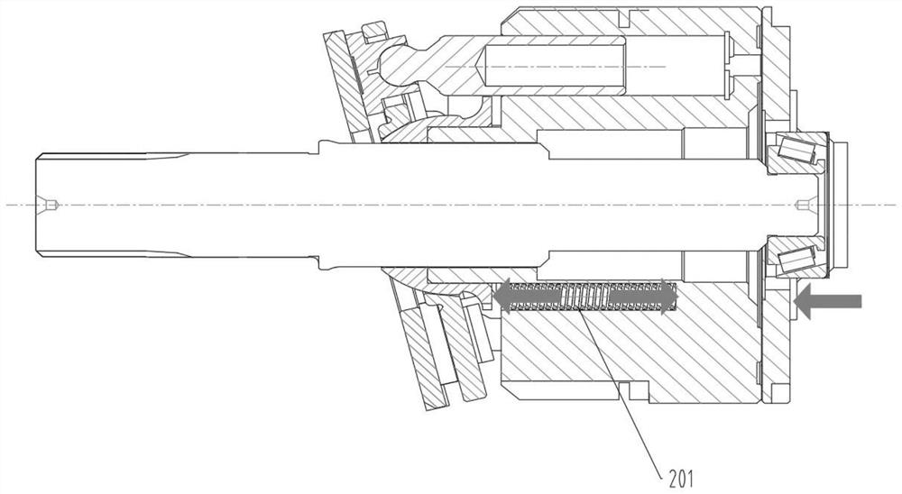
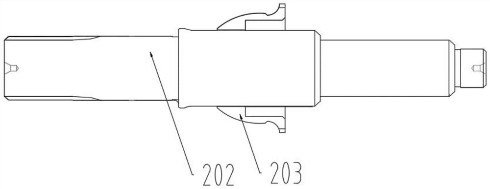
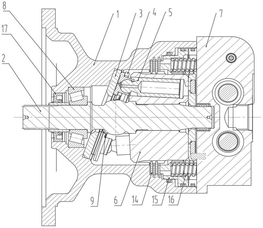
[0019] like Figure 3-5 As shown, an integral output shaft hydraulic motor includes a casing 1, an integral output shaft 2, a thrust plate 3, a return plate 4, a plunger 5, a cylinder block 6 and an end cover 7; the casing 1 There is an inclined thrust plate limit surface inside, the thrust plate 3 is arranged on the rear side of the thrust plate limit surface; the cylinder body 6 is arranged in the casing 1, the column The plug 5 is circumferentially arranged on the outer side of the integral output shaft 2 . One end of the plunger 5 extends into the predetermined plunger cavity in the cylinder block 6 , and the other end passes through the return disc 4 and abuts against the rear of the thrust disc 3 . on the surface;
[0020] The integral output shaft 2 is arranged on the axis in the housing 1, and the integral output shaft 2 is provided with a front contact section A, a spherical section B, a middle contact section C, a synchronization section D and a The rear contact section E; the front contact section A of the integral output shaft 2 is rotatably connected to the front end of the housing 1 through the front bearing 8; The surface is elastically connected; the middle contact section C is a convex ring shoulder, and the convex ring shoulder abuts the front end of the cylinder block 6; the synchronization section D is set in the cylinder block 6 and connected with the cylinder block 6; the rear contact section E Passing through the valve plate 10, and rotatably connected with the end cover 7 through the rear bearing 11;
[0021] The end cover 7 is arranged at the rear end of the housing 1 , the valve plate 10 abuts on the rear end of the cylinder 6 on one side, and abuts on the floating piston ring 12 on the other side. A corrugated spring 13 is arranged at the front end of the end cover 7 and between the floating piston ring 12 and the end cover 7 .
[0022] In this embodiment, the housing 1 is provided with a brake chamber, the brake chamber is located on the radial outer side of the cylinder, and the brake chamber is provided with a parking brake friction plate 14 and a brake piston 15 . , the brake friction plate 14 is connected with the brake piston 15 , and a brake spring 16 is arranged between the brake piston 15 and the housing 1 .
[0023] In this embodiment, the front bearing 8 is a tapered roller bearing.
[0024] In this embodiment, the rear bearing 11 is a needle roller bearing.
[0025] In this embodiment, a rotary oil seal 17 is provided between the front contact section A of the integral output shaft 2 and the housing 1 , and the rotary oil seal 17 is located outside the front bearing 8 .
[0026] The above descriptions are only preferred embodiments of the present invention, and are not intended to limit the present invention. Any modification, equivalent replacement, improvement, etc. made within the spirit and principle of the present invention shall be included in the scope of the present invention. within the scope of protection.

PUM

no PUM

Description & Claims & Application Information

We can also present the details of the Description, Claims and Application information to help users get a comprehensive understanding of the technical details of the patent, such as background art, summary of invention, brief description of drawings, description of embodiments, and other original content. On the other hand, users can also determine the specific scope of protection of the technology through the list of claims; as well as understand the changes in the life cycle of the technology with the presentation of the patent timeline. Login to view more.

Similar technology patents

Method and device for calibrating clock frequency

Owner:DATANG MICROELECTRONICS TECH CO LTD

Recycled aggregate pretreatment equipment

Owner:XIAMEN TIANRUN JINLONG BUILDING MATERIAL

Detection method for building change by multispectral image

ActiveCN103077515Anarrow downReduce the impact
Owner:NORTH CHINA UNIVERSITY OF TECHNOLOGY

Classification and recommendation of technical efficacy words

  • Not easy to heat deformation
  • Reduce the impact

Bi-component epoxy resin binder, cast mixture containing bi-component epoxy resin binder, cast molding body and method for casting metal products

ActiveCN102581216ANot easy to heat deformationImprove casting quality
Owner:JINAN SHENGQUAN GROUP SHARE HLDG

Clutch pressure plate

InactiveCN110630650Aincrease stiffnessNot easy to heat deformation
Owner:JIANGSU UNIV

Method and system for searching images by images based on deep learning

ActiveCN104679863Areduce dimensionalityReduce the impact
Owner:武汉众智数字技术有限公司

Method and device for determining access point position

Owner:BEIJING SANKUAI ONLINE TECH CO LTD

Method and apparatus for measuring cofocal combined ultra-long focal distance

InactiveCN101408478AReduce the measurement optical path lengthReduce the impact
Owner:BEIJING INSTITUTE OF TECHNOLOGYGY

Array substrate and detection method thereof and display device

InactiveCN107422560AReduce reflectionsReduce the impact
Owner:BOE TECH GRP CO LTD
Why Eureka
Try Eureka