Low-temperature-resistant stainless steel flange and punching machining die thereof

A technology for processing molds and stainless steel, applied in the field of flanges, can solve problems such as unsatisfactory standard flange parts, unfavorable installation, inconvenient adjustment and installation, etc., and achieve the effect of quick installation, favorable installation and convenient adjustment and installation

Pending Publication Date: 2021-06-18
SUZHOU CHENGJIAN FLANMFG
View PDF0 Cites 4 Cited by
  • Summary
  • Abstract
  • Description
  • Claims
  • Application Information

AI Technical Summary

Problems solved by technology

However, with the upgrading and development of manufacturing technology in related fields, some fields have special requirements for the installation and connection of flanges, and standard flanges cannot meet the relevant requirements.
[0003] At present, low-temperature resistant stainless steel flanges are designed for the use of lifting flanges, but the size of existing low-temperature resistant stainless steel flanges is fixed, and it is inconvenient to adjust and install during actual installation and use, which is not conducive to installation

Method used


Image

  • Low-temperature-resistant stainless steel flange and punching machining die thereof
  • Low-temperature-resistant stainless steel flange and punching machining die thereof
  • Low-temperature-resistant stainless steel flange and punching machining die thereof

Examples


Embodiment 1

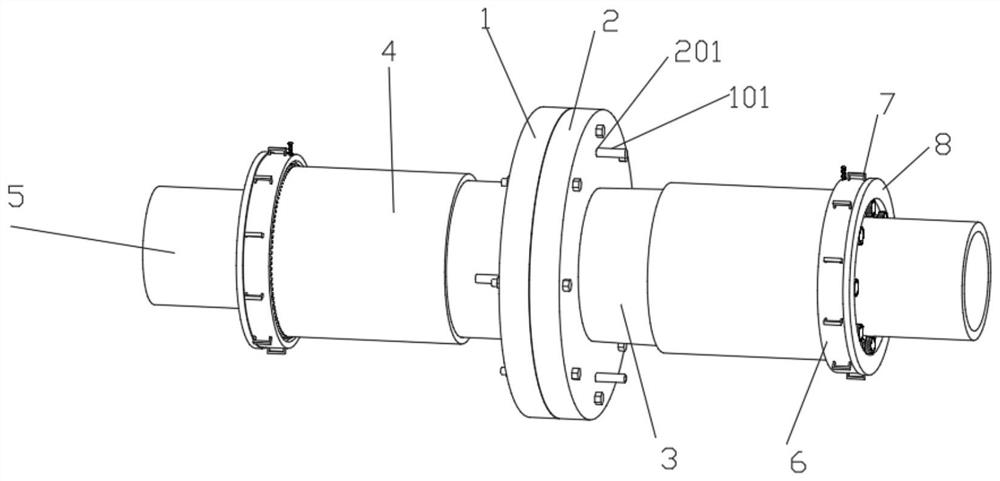
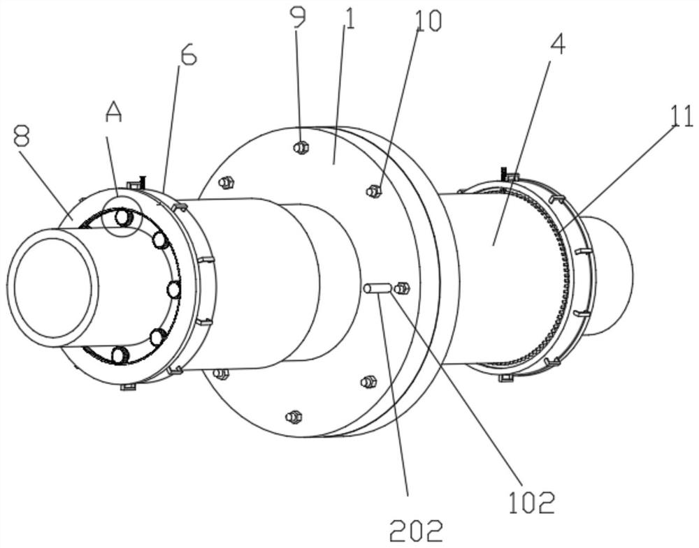
[0038] like Figure 1-5As shown, a low-temperature-resistant stainless steel flange includes a first flange 1 and a second flange 2, the first flange 1 and the second flange 2 are connected with a guide structure, and the guide structure includes a first guide Rod 101, first guide hole 102, second guide hole 201 and second guide rod 202, the first guide rod 101 is symmetrically set on the right side wall of the first flange 1, and the second guide hole 201 is symmetrically set on the second On the side wall of the flange 2, the first guide rod 101 is symmetrically fixed on the right side wall of the first flange 1, and the second guide hole 201 is symmetrically opened on the side wall of the second flange 2, and the first guide The outer wall of the rod 101 is fitted and slidably connected with the inner wall of the second guide hole 201, and the inner wall of the first guide hole 102 is fitted and slidably connected with the outer wall of the second guide rod 202. The length ...

Embodiment 2

[0044] Embodiment 2 is a further improvement to Embodiment 1.

[0045] like Figure 6-8 A punching die for a low-temperature-resistant stainless steel flange is shown, including an upper die 22 and a lower die 25, the upper die 22 is connected to the driving structure, the lower die 25 is fixed and installed, and the bottom of the upper die 22 is formed according to the first flange The mounting hole position of 1 is fixedly connected with a punching rod 24, the mounting hole position of the first flange plate 1 on the top of the lower mold 25 is provided with a punching hole 36, and the top of the lower mold 25 is symmetrically fixedly connected with a third guide rod 30, the first A flange 1 is fitted and slidably connected with the third guide rod 30 through the first guide hole 102, the bottom of the lower mold 25 is fixedly connected with the sleeve 26, and the bottom of the sleeve 26 is fixedly connected with the mounting frame 27, and the mounting frame 27 is fixed Con...


PUM


Abstract

The invention discloses a low-temperature-resistant stainless steel flange and a punching machining die thereof, and relates to the technical field of flanges. The low-temperature-resistant stainless steel flange comprises a first flange plate and a second flange plate, wherein the first flange plate and the second flange plate are connected with a guide structure; the first flange plate and the second flange plate are connected with mounting threaded columns in an inserted mode through mounting holes, and the left ends of the mounting threaded columns are in threaded connection with nuts; and the outer wall of the first flange plate and the outer wall of the second flange plate are fixedly connected with a transverse pipe, and the transverse pipe is connected with a length adjusting structure for adjusting the length. In this way, the size of the stainless steel flange can be conveniently adjusted according to the actual situation, adjusting and mounting are facilitated during actual mounting and using, and mounting is facilitated.

Description

technical field [0001] The invention relates to the technical field of flanges, in particular to a low-temperature resistant stainless steel flange and a punching processing mold thereof. Background technique [0002] Flanges are parts that are connected to each other between shafts and are mainly used for connection between pipe ends. The use of flanges has a long history. At present, the country has relevant standard classifications for flanges, such as classification according to mechanical structure standards. Flanges include integral flanges, butt welding flanges, plate flat welding flanges, butt welding ring plate loose sleeve flanges, flat welding ring plate loose sleeve flanges, flanging ring plate loose sleeve flanges, flange covers and other products . These products are widely used in many fields. However, with the upgrading and development of manufacturing technology in related fields, some fields have special requirements for flange installation and connectio...

Claims


Application Information

Patent Timeline
Patent Type & Authority Applications(China)
IPC IPC(8): F16B7/18F16B7/20F16B7/00B21D28/04B21D28/34
CPCB21D28/04B21D28/34F16B7/00F16B7/182F16B7/20
Inventor 王勇张健张才明吕荣华周驰
Owner SUZHOU CHENGJIAN FLANMFG
Why Eureka
Try Eureka