Partial discharge ultrasonic detection device

A detection device and partial discharge technology, which is applied in the field of ultrasonic detection, can solve the problems of increased operation risk, movement deformation, inaccurate test results, etc., and achieve the effect of improving detection accuracy and facilitating adjustment

Active Publication Date: 2021-06-18
HUAIYIN TEACHERS COLLEGE
View PDF6 Cites 10 Cited by
  • Summary
  • Abstract
  • Description
  • Claims
  • Application Information

AI Technical Summary

Problems solved by technology

[0003] The existing partial discharge ultrasonic detection requires the operator to hold the sensor for a long time for detection, which is easy to make the operator fatigued and deformed, which in turn leads to inaccurate test results. At the same time, it increases the risk of operation and cannot meet the needs of actual use. The existing partial discharge ultrasonic detection has the disadvantages of manual testing and low detection accuracy, and it is difficult to be popularized and applied

Method used


Image

  • Partial discharge ultrasonic detection device
  • Partial discharge ultrasonic detection device
  • Partial discharge ultrasonic detection device

Examples


Embodiment 1

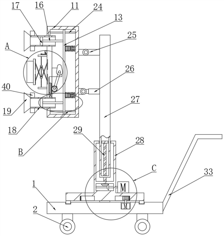
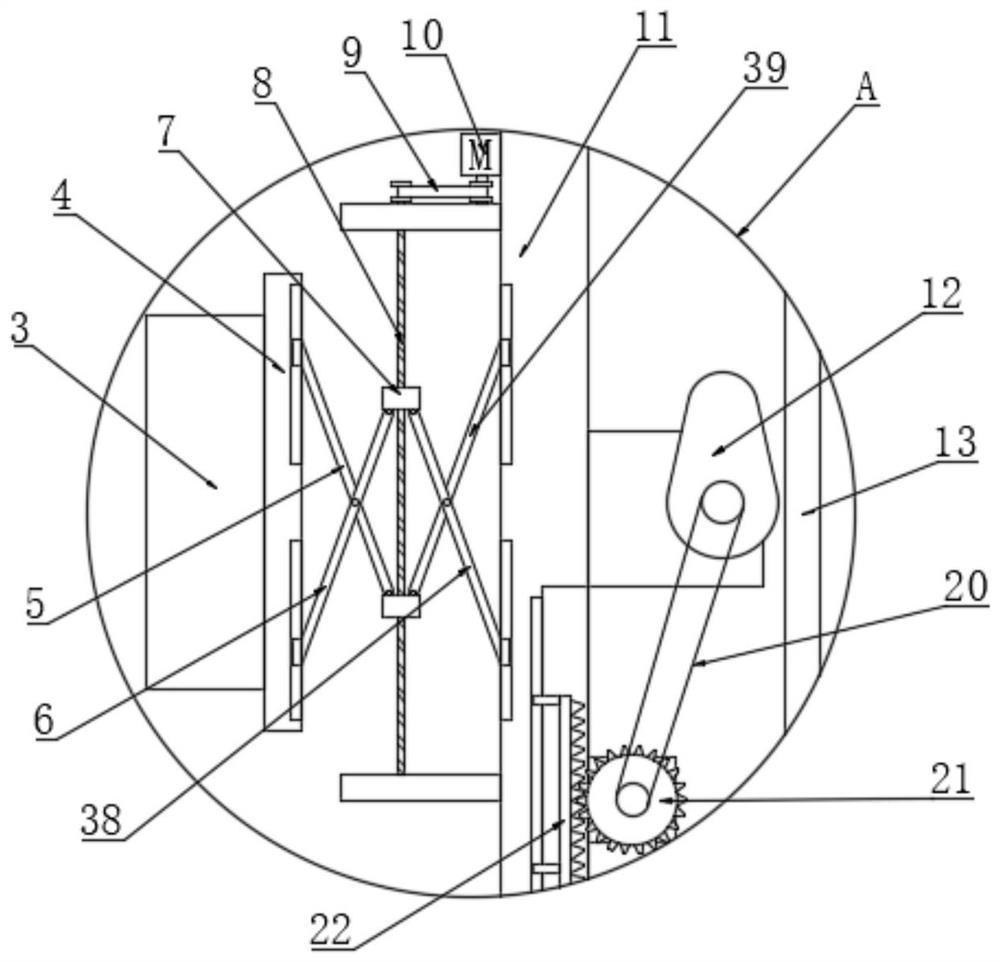
[0028] see Figure 1 to Figure 6 , a partial discharge ultrasonic detection device, including a base 1, the bottom of the base 1 is provided with a universal wheel 2 for easy movement, and the top of the base 1 is provided with an ultrasonic sensor 3 for easy detection, and the ultrasonic sensor 3 passes The support plate 4 is connected with a linear drive assembly, and the linear drive assembly includes a first connecting rod 5, a second connecting rod 6, a connecting seat 7, a first screw 8, a third connecting rod 38, a fourth connecting rod 39 and a first The motor 10, the first connecting rod 5 and the second connecting rod 6 are rotatably connected by a rotating shaft, the third connecting rod 38 and the fourth connecting rod 39 are rotatably connected by a rotating shaft, and the connecting seat 7 is threadedly connected to the first screw rod 8, the first screw 8 is connected to the output shaft of the first motor 10 through the first synchronous belt 9. The outer side ...

Embodiment 2

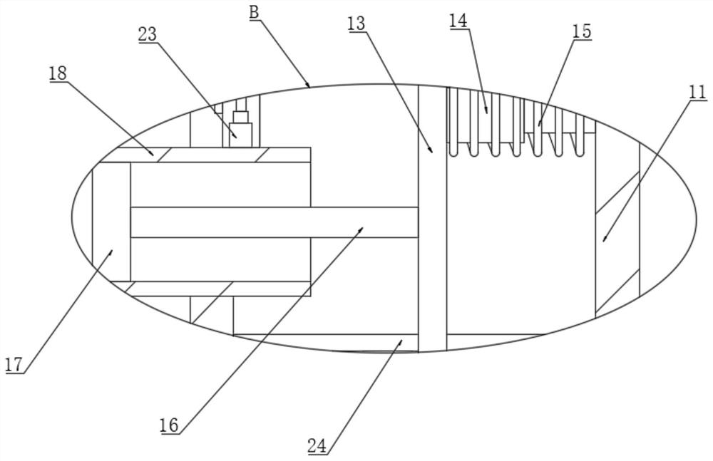
[0038] see Figure 1 to Figure 6 , a partial discharge ultrasonic detection device, including a base 1, the bottom of the base 1 is provided with universal wheels 2 for easy movement, the top of the base 1 is provided with an ultrasonic sensor 3 for easy detection, and also includes a connection box 11, The connection box 11 is hinged on the lifting column 27 through the hinged seat 25, the cylinder 26 for pitch adjustment is arranged below the hinged seat 25, the lifting column 27 is slidably connected to the lifting base 28, and the lifting column 27 The connection with the lifting base 28 is provided with a lifting drive assembly, and the lifting drive assembly includes a second screw rod 29, a first bevel gear 30, a second bevel gear 31 and a second motor 32, and the lifting column 27 is screwed On the second screw rod 29, the lifting base 28 is rotatably connected to the base 1 through the connecting shaft 37 and the slider. The drive assembly includes a second gear 35 a...


PUM


Abstract

The invention discloses a partial discharge ultrasonic detection device, belongs to the technical field of ultrasonic detection, and solves the problems of manual test and low detection precision in the existing partial discharge ultrasonic detection. The device has the technical key points that the partial discharge ultrasonic detection device comprises a base, universal wheels are pushed to facilitate movement of the device, a suction cup is in contact with a to-be-detected shell, an electric telescopic rod drives a rack to stretch out and draw back to enable a cam to rotate, so that a piston plate is subjected to pressure suction, an annular magnet reinforces stability, a first motor is started to drive connecting bases to get close to and get away from each other, the position of an ultrasonic sensor is conveniently adjusted, and pitching adjustment detection of the ultrasonic sensor is conveniently achieved through a hinge base and an air cylinder; a second motor is started to drive a lifting column to drive the ultrasonic sensor to perform lifting adjustment in the height direction, a third motor is started to drive a lifting base to drive the ultrasonic sensor to perform rotation detection under the action of a connecting shaft and a sliding block, and the device has the advantages of saving labor and being high in detection precision.

Description

technical field [0001] The invention relates to the field of ultrasonic detection, in particular to a partial discharge ultrasonic detection device. Background technique [0002] Partial discharge refers to the discharge phenomenon that occurs in the local area of ​​the insulation structure of the power equipment under the action of a sufficiently strong electric field. Although this kind of partial discharge will only lead to partial breakdown of the insulation structure and local short circuit, and no penetrating breakdown of the insulation between the conductors of the power equipment, each partial discharge will have some impact on the insulating medium. In addition, slight partial discharge has little effect on the insulation of power equipment, and the insulation strength drops slowly, while strong partial discharge will make the insulation strength drop quickly. Therefore, when the partial discharge reaches and exceeds a certain level, it will cause damage to the tra...

Claims


Application Information

Patent Timeline
Patent Type & Authority Applications(China)
IPC IPC(8): G01R31/12
CPCG01R31/1209
Inventor 张韩飞茹勉
Owner HUAIYIN TEACHERS COLLEGE
Why Eureka
Try Eureka