
Injector batch destroying device

A technology for destroying devices and syringes, applied to hypodermic injection devices, devices introduced into the body, needles, etc., can solve the problems of not having disinfection and screening functions, and achieve the effect of easy collection

Active Publication Date: 2021-06-22
南京市淑先科技有限公司
View PDF6 Cites 1 Cited by
  • Summary
  • Abstract
  • Description
  • Claims
  • Application Information

AI Technical Summary

Problems solved by technology

[0004] This device can destroy syringes, but it does not have the functions of disinfection and screening, so now a syringe batch destruction device that can realize multiple functions of destruction, disinfection and screening is developed

Method used


Image

  • Injector batch destroying device
  • Injector batch destroying device
  • Injector batch destroying device

Examples


Embodiment 1

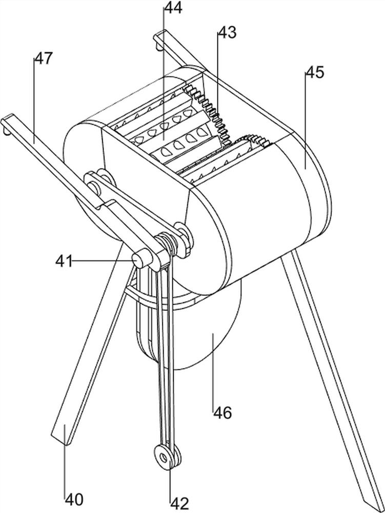
[0078] A syringe bulk destruction device, such as Figure 1-3 As shown, it includes a base plate 1, a support column 2, a waste transport mechanism 3 and a destruction mechanism 4. Two support columns 2 are provided on the front side of the base plate 1, and a waste material transport mechanism 3 is provided on the base plate 1. The rear side of the base plate 1 is connected to the waste material A destruction mechanism 4 is connected between the transportation mechanisms 3 .

[0079] The waste transport mechanism 3 includes a support seat 30, a servo motor 31, a first bearing seat 32, a first rotating shaft 33 and a first belt assembly 34, the left rear side of the bottom plate 1 is provided with a support seat 30, and the support seat 30 is provided with a servo motor 31. The three sides of the base plate 1 are provided with first bearing seats 32, and the first bearing seats 32 on the same lateral side at the front are rotatably connected with a first rotating shaft 33, and...

Embodiment 2

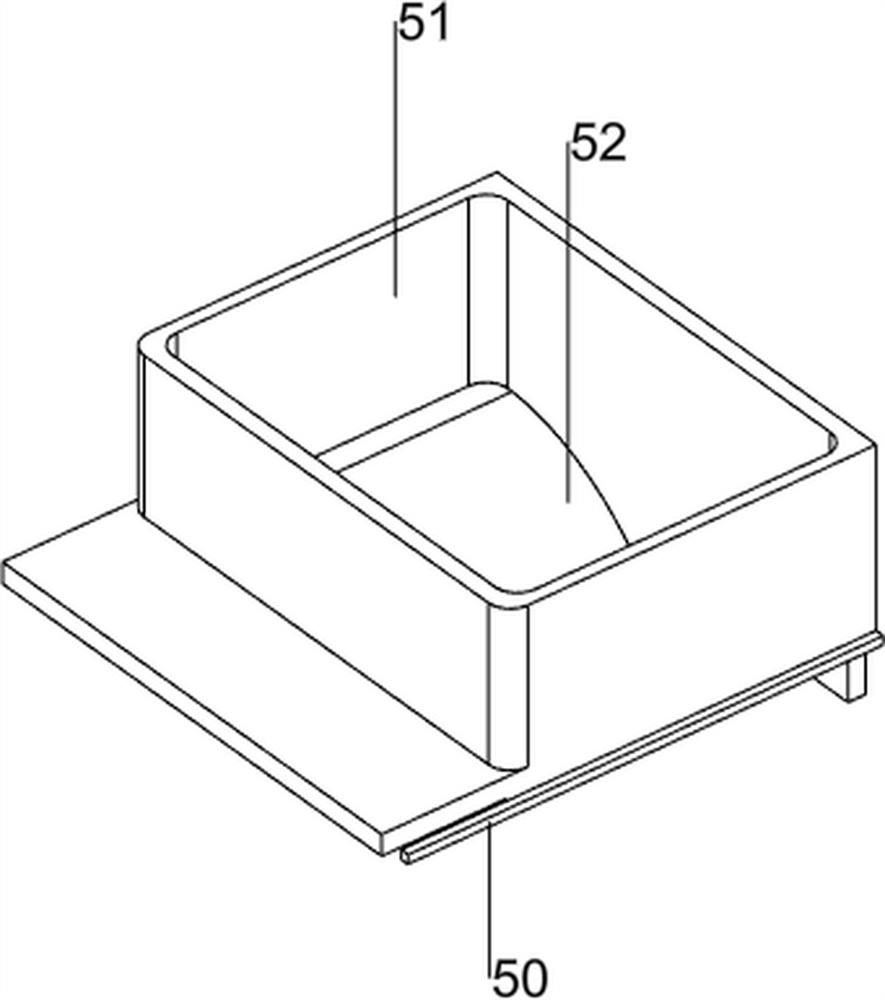
[0083] On the basis of Example 1, such as Figure 4-9 As shown, a feeding mechanism 5 is also included, and the feeding mechanism 5 includes a second connecting plate 50, a material box 51 and a slide plate 52, and the left and right sides of the upper part of the protective shell 45 are connected with the second connecting plate 50, and the second connecting plate A material box 51 is connected to the material box 50, and slide plates 52 are provided on the left and right sides of the material box 51 bottom.

[0084] When people need to feed materials, the syringe can be poured into the material box 51 and dropped down into the protective shell 45 through the slide plate 52 .

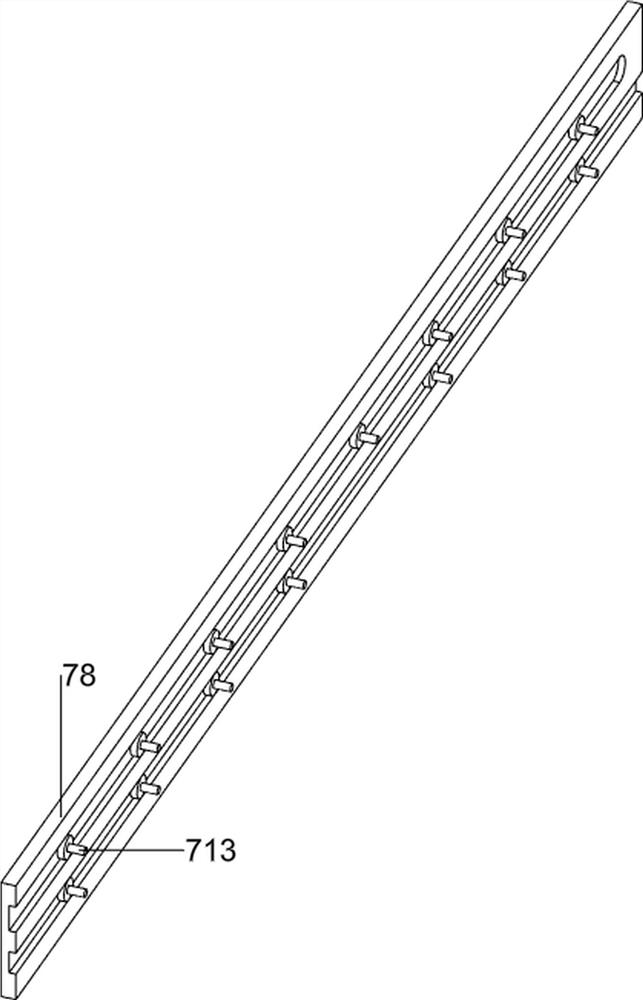
[0085] Also includes an automatic disinfection mechanism 6, the automatic disinfection mechanism 6 includes a third connecting plate 60, a first slide rail 61, a connecting rod 62, a disinfectant storage tank 63, a disinfectant addition port 64, a U-shaped plate 65, and a wedge-shaped block 66 , a rou...


PUM


Abstract

The invention relates to a destroying device, in particular to an injector batch destroying device, and aims to provide the injector batch destroying device which can realize multiple functions of destroying, disinfecting and screening. The injector batch destroying device comprises a bottom plate and supporting columns, wherein the two supporting columns are arranged on one side of the bottom plate; a waste conveying mechanism which is arranged on the bottom plate; and a destroying mechanism which is connected between one side of the bottom plate and the waste conveying mechanism. Through cooperation of the waste conveying mechanism, the destroying mechanism and the feeding mechanism, the injector can be automatically destroyed, and then the injector is conveyed.

Description

technical field [0001] The invention relates to a destruction device, in particular to a batch destruction device for syringes. Background technique [0002] In order to prevent cross-infection caused by the reuse of used disposable syringes, it is necessary to destroy the used disposable syringes on the spot to meet the requirements of "needle and barrel separation, needle and barrel destruction". In order to achieve this goal, people have developed Lots of syringe destroyers. [0003] Patent application CN201520436936.9 A clinical syringe destruction device, its structure includes a cuboid-shaped frame with an open top, hooks arranged at the bottom of the frame, and support legs arranged at the four corners of the bottom of the frame. The telescopic baffle is divided into upper and lower parts, in which the upper sensor is installed on the inner wall of the upper part, and the destruction channel is set in the lower part, and cutters are arranged alternately on both sides...

Claims


Application Information

Patent Timeline
Patent Type & Authority Applications(China)
IPC IPC(8): A61M5/32A61L2/18
CPCA61M5/3205A61L2/18Y02W30/62
Inventor 莫利生
Owner 南京市淑先科技有限公司
Learn More