Novel air bag type pneumatic mechanical claw

A mechanical claw and airbag technology, applied in the field of new airbag pneumatic mechanical claw, can solve the problems of high-speed application, such as inability, slow grasping speed, complex structure, etc., to achieve low cost of use and maintenance, easy to use and adapt to powerful effect

Pending Publication Date: 2021-06-22
合肥皓瀚智能科技有限公司
View PDF0 Cites 4 Cited by
  • Summary
  • Abstract
  • Description
  • Claims
  • Application Information

AI Technical Summary

Problems solved by technology

The advantages of pneumatic mechanical claws are simple structure, easy maintenance, and fast grasping speed; the disadvantage is that the angle of opening and closing cannot be controlled, and it cannot adapt well to objects of different shapes and sizes, and it may even cause damage to soft and fragile objects. damage
The advantage of the electric mechanical claw is that it can control the opening and closing angle according to the size of the grasped object, but the structure is relatively complicated, the grasping speed is slow, and it is powerless for high-speed applications; in summary, the present invention designs a A new airbag-type pneumatic mechanical gripper solves this problem

Method used


Image

  • Novel air bag type pneumatic mechanical claw
  • Novel air bag type pneumatic mechanical claw
  • Novel air bag type pneumatic mechanical claw

Examples


Embodiment 1

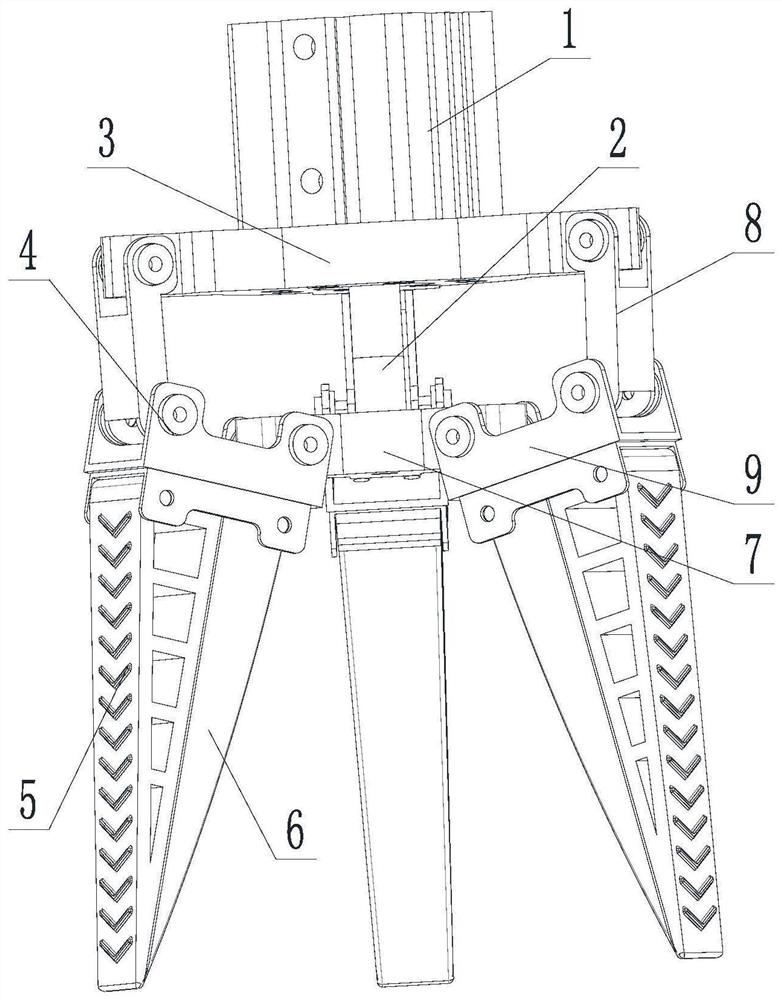
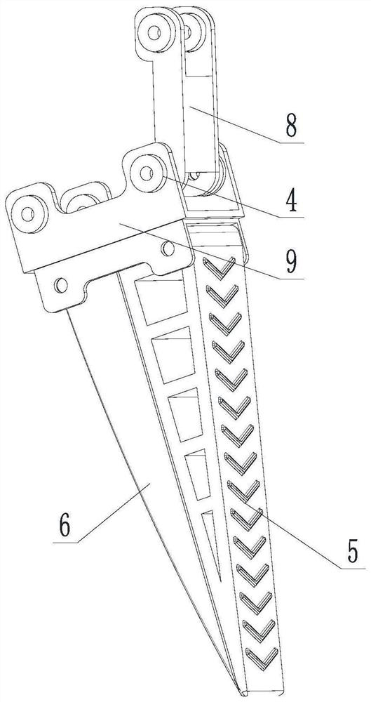
[0021] see Figure 1-2 , a new airbag-type pneumatic mechanical claw, including a fixed platform 3 and a mechanical claw body, the mechanical claw body includes a plurality of flexible grasping fingers 5 that can be deformed and bent, and the fixed platform 3 is fastened to the main cylinder 1 by screws Above, the main cylinder 1 has a built-in piston, and the piston is connected with a linkage shaft 2 whose lower end extends out of the main cylinder 1. The lower end of the linkage shaft 2 runs through the fixed platform 3 and extends below the fixed platform 3, and the end of the linkage shaft 2 is connected with a motion platform 7 , the mechanical claw is located at the bottom of the fixed platform 3, the top of the flexible grabbing finger 5 is provided with a finger fixing seat 9, the outer end of the finger fixing seat 9 is rotationally connected with the finger connector 8 through the bearing 4, and the inner end of the flexible grabbing finger 5 passes through the beari...

Embodiment 2

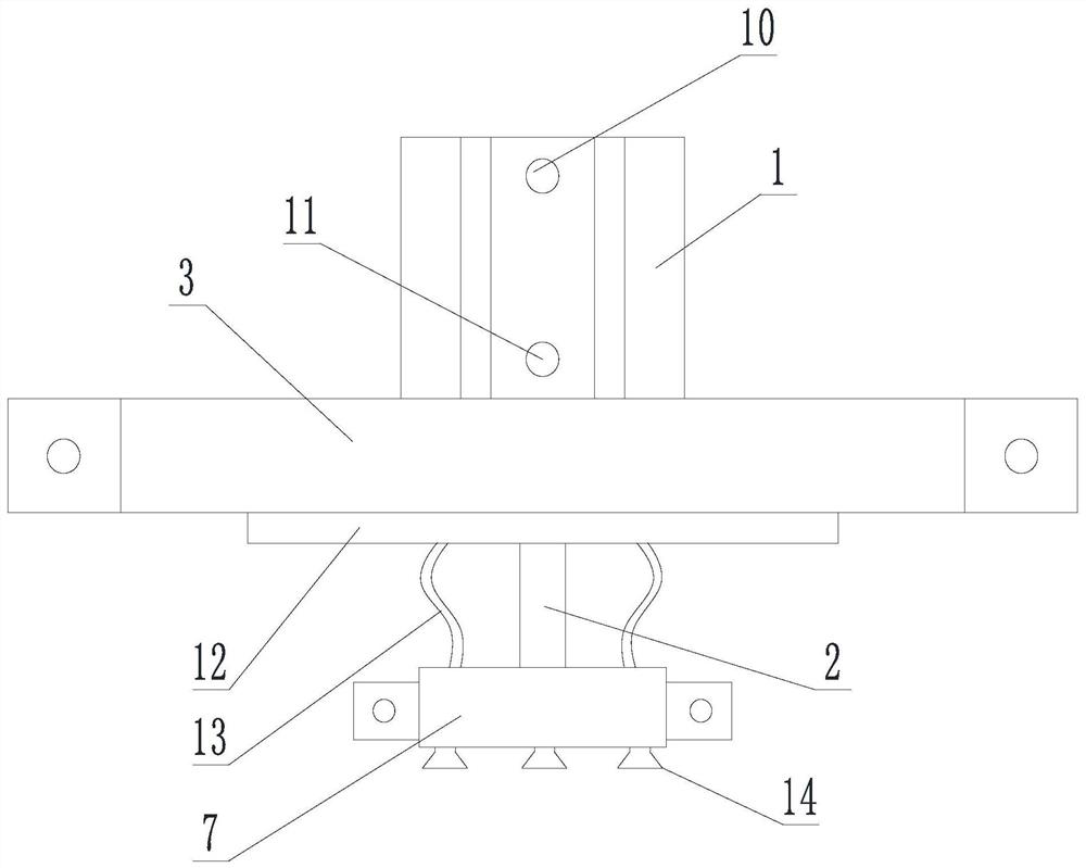
[0027] refer to image 3 , on the basis of Embodiment 1, when actually grabbing, in order to further ensure the stability of grabbing, a plurality of negative pressure suction cups 14 are also provided at the bottom of the moving platform 7, and the negative pressure suction cups 14 are downward openings. Trumpet-shaped, between the moving platform 7 and the fixed platform 3, there are a plurality of negative pressure connecting pipes 13 corresponding to the negative pressure suction cups 14 and sealingly docked, and the upper ends of the negative pressure connecting pipes 13 are sealed and docked with the distribution air pipe 12. The distribution air pipe 12 is attached to the bottom surface of the fixed platform 3. When grabbing large-scale items, the position of the moving platform 7 is firstly controlled by the master cylinder 1, and the expansion of the flexible airbag 6 is adjusted to ensure that the size of the item is consistent with the grab. At the same time, the ne...

Embodiment 3

[0029] refer to Figure 4 On the basis of Embodiment 2, the device also includes a pneumatic control system, the pneumatic control system includes a main controller 15, and the main controller 15 is connected to the main cylinder 1, the air bag valve controller 16 and the negative pressure valve 18, The airbag valve controller 16 is connected with a plurality of airbag valves 17, the number of the airbag valves 17 is the same as that of the flexible airbag 6 and connected one by one, the airbag valve 17 has an exhaust pipe and an intake pipe, and the negative pressure valve 18 Connect the distribution air pipe 12.

[0030] Through the centralized control of the main controller 15 in the pneumatic control system, the inflation and deflation of different structures can be reasonably distributed, and through the setting of multiple independent airbag valves 17 and airbag valve controllers 16, irregular objects When grabbing, the expansion of each flexible airbag 6 can also be in...


PUM


Abstract

The invention discloses a novel air bag type pneumatic mechanical claw. The claw comprises a fixed platform and a mechanical claw body, the mechanical claw body comprises a plurality of flexible grabbing fingers capable of deforming and bending, the fixed platform is fastened to a main air cylinder through screws, a piston is arranged in the main air cylinder, the piston is connected with a linkage shaft, and the lower end of the linkage shaft extends out of the main air cylinder. The lower end of the linkage shaft penetrates through the fixed platform and extends out of the lower portion of the fixed platform, the tail end of the linkage shaft is connected with a moving platform, the mechanical claw is located at the bottom of the fixed platform, finger fixing bases are arranged at the tops of the flexible grabbing fingers, and the outer ends of the finger fixing bases are rotationally connected with finger connecting pieces through bearings. The mechanical claw is driven by compressed air, on the premise that high-speed grabbing is guaranteed, control over the opening and closing angle is achieved, meanwhile, the mechanical claw has the advantages that a traditional pneumatic mechanical claw is easy to maintain and easy to drive, the mechanical claw can effectively adapt to objects of various sizes, shapes and materials, and meanwhile damage-free rapid grabbing of soft and vulnerable objects is achieved.

Description

technical field [0001] The invention relates to the field of production automation, in particular to a novel air bag type pneumatic mechanical claw. Background technique [0002] In modern agricultural and industrial production, various types of mechanical claws, as end effectors, play a very important role in the application of grabbing and placing products. Such as palletizing, sorting, packaging, etc. The application of mechanical claws in various industries has greatly reduced the work intensity of production line workers, greatly improved production efficiency, and further promoted the process of modern industrial and agricultural production. [0003] At present, the more commonly used multi-finger mechanical claws in the market are mainly divided into two types: pneumatic and electric. The advantages of pneumatic mechanical claws are simple structure, easy maintenance, and fast grasping speed; the disadvantage is that the angle of opening and closing cannot be contro...

Claims


Application Information

Patent Timeline
Patent Type & Authority Applications(China)
IPC IPC(8): B25J15/00B25J15/06B25J15/10
CPCB25J15/0023B25J15/0616B25J15/0683B25J15/10
Inventor 钟作锦曹东华邵帅
Owner 合肥皓瀚智能科技有限公司
Why Eureka
Try Eureka