Anti-pollution treatment equipment for medical waste of emergency department
A processing equipment and anti-pollution technology, which can be used in trash cans, garbage collection, garbage cleaning, etc., and can solve problems such as secondary pollution
- Summary
- Abstract
- Description
- Claims
- Application Information
AI Technical Summary
Problems solved by technology
Method used
Image
Examples
specific Embodiment approach 1
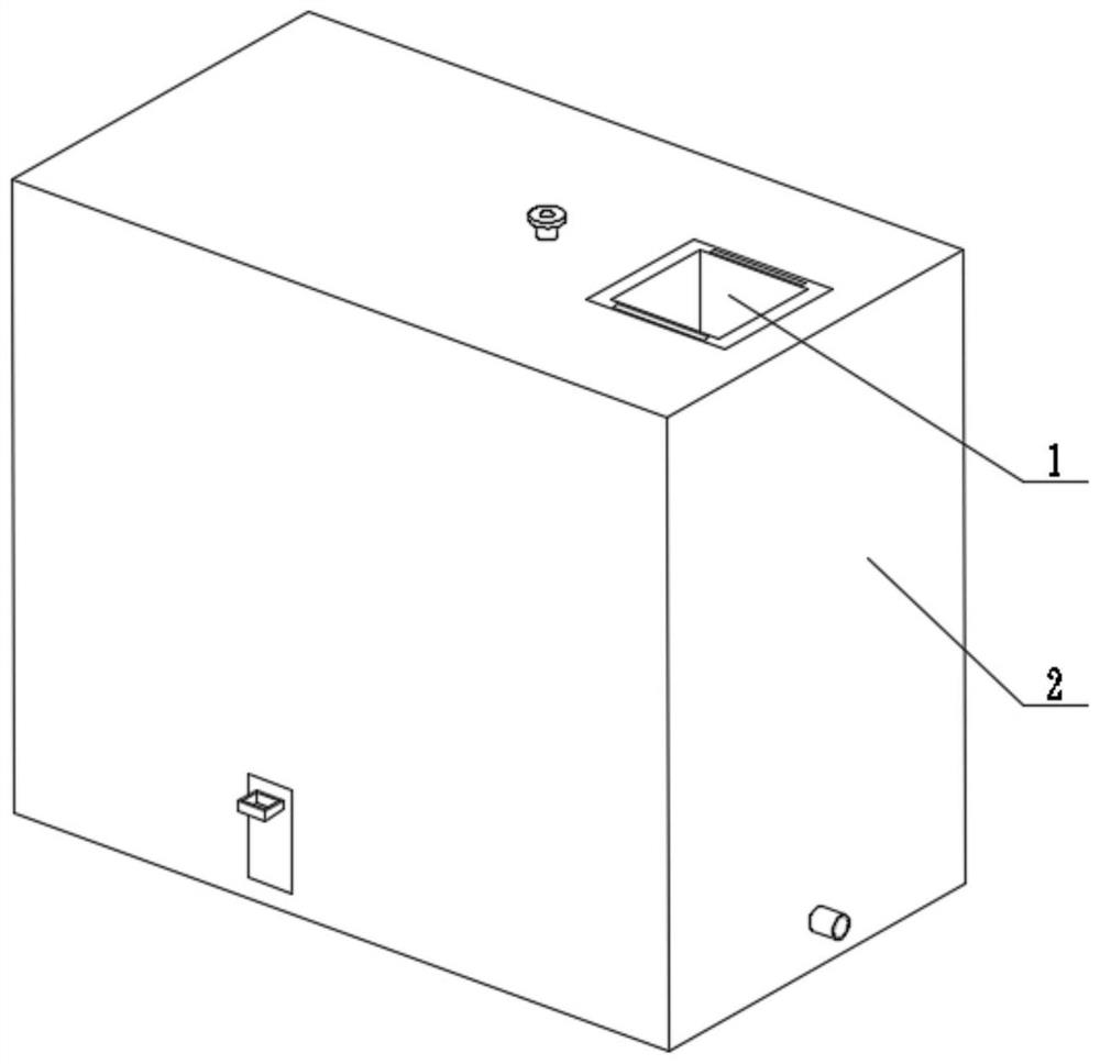
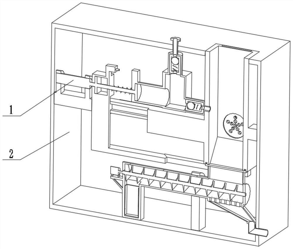
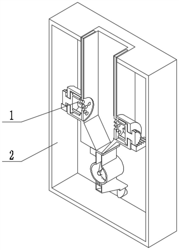
[0026] Combine below figure 1 , figure 2 , image 3 , Figure 4 , Figure 5 , Image 6 , Figure 7 , Figure 8 , Figure 9 , Figure 10 , Figure 11 Describe this embodiment, the present invention relates to a medical waste treatment equipment, more specifically, an emergency department medical waste anti-pollution treatment equipment, including an anti-pollution disinfection mechanism 1 and a shell mechanism 2, and the equipment can use a cylinder to push and complete disinfection at one time The disinfectant is sprayed and disinfected, and the gate is opened to provide time for disinfection, and then the gate is opened to complete the unloading and transport the garbage for a certain distance. The equipment can recycle the garbage collected after disinfection.
[0027] The anti-pollution disinfection mechanism 1 is connected with the shell mechanism 2 .
specific Embodiment approach 2
[0029] Combine below figure 1 , figure 2 , image 3 , Figure 4 , Figure 5 , Image 6 , Figure 7 , Figure 8 , Figure 9 , Figure 10 , Figure 11Describe this embodiment, this embodiment will further explain the first embodiment, the anti-pollution disinfection mechanism 1 includes a connection seat 1-1, a recovery box 1-2, a passive slope seat 1-3, a mixed flow cylinder 1-4, a belt Shaft gear 1-5, rack 1-6, double hole limit seat 1-7, connecting rod 1-8, sliding seat 1-9, cross chute 1-10, cylinder 1-11, movable plug 1-12 , slide rod 1-13, spring 1-14, fixed socket 1-15, compression tube 1-16, transfer box 1-17, flanged tube 1-18, suction tube 1-19, ejection tube 1-20 , inlet 1-21, filter plate 1-22, filter plate groove 1-23, sliding gate 1-24, cylinder rod 1-25, delay push seat 1-26, piston 1-27, liquid inlet check valve 1-28, ejection check valve 1-29, ejection pipe I1-30, limit rod 1-31, gate chute 1-32, stirring wheel 1-33, inner slope 1-34, discharge port ...
specific Embodiment approach 3
[0031] Combine below figure 1 , figure 2 , image 3 , Figure 4 , Figure 5 , Image 6 , Figure 7 , Figure 8 , Figure 9 , Figure 10 , Figure 11 Describe this embodiment, this embodiment will further explain Embodiment 1, the shell mechanism 2 includes a waste liquid pipe 2-1, a shell body 2-2, a waste material collection box 2-3, and a waste material collection box matching groove 2-4 , Wear outlet 2-5, feed inlet I2-6, conveying body 2-7, conveying falling port 2-8, motor 2-9, screw shaft 2-10, auxiliary support 2-11, connection port 2-12 , discharge hole 2-13, collecting bucket 2-14, the waste liquid pipe 2-1 penetrates into the shell body 2-2 and is connected with the collecting bucket 2-14, and the collecting bucket 2-14 is connected with the conveying body 2-7, The waste material collection box 2-3 is slidingly connected with the waste material collection box matching groove 2-4 arranged on the shell body 2-2, and the piercing port 2-5 and the feeding port...
PUM
 Abstract
Description
Claims
Application Information
 - R&D
- Intellectual Property
- Life Sciences
- Materials
- Tech Scout
- Unparalleled Data Quality
- Higher Quality Content
- 60% Fewer Hallucinations
Browse by: Latest US Patents, China's latest patents, Technical Efficacy Thesaurus, Application Domain, Technology Topic, Popular Technical Reports.
© 2025 PatSnap. All rights reserved.Legal|Privacy policy|Modern Slavery Act Transparency Statement|Sitemap|About US| Contact US: help@patsnap.com


