Method and apparatus for transferring data on bus to or from device to be controlled by said bus

A bus transmission and bus technology, which is applied in the field of transmitting data and equipment to a device on the bus or from the device to the bus, and can solve problems such as bus blocking.

Inactive Publication Date: 2003-12-03
THOMSON LICENSING SA
View PDF2 Cites 0 Cited by
  • Summary
  • Abstract
  • Description
  • Claims
  • Application Information

AI Technical Summary

Problems solved by technology

Therefore, the bus is blocked for an indeterminate period of time because the access granted by the bus cannot be overridden by the physical layer.
Bus lock is serious, it means that the whole bus is blocked, no other nodes can access the bus to send data

Method used


Image

  • Method and apparatus for transferring data on bus to or from device to be controlled by said bus
  • Method and apparatus for transferring data on bus to or from device to be controlled by said bus
  • Method and apparatus for transferring data on bus to or from device to be controlled by said bus

Examples


Embodiment Construction

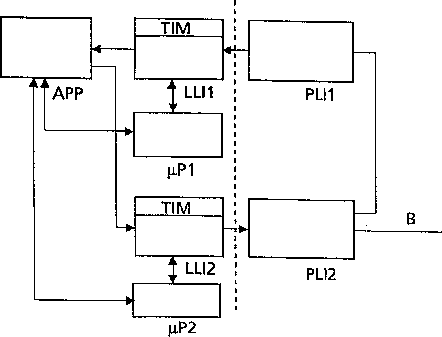
[0036] exist figure 1Among them, the first physical layer integrated circuit PLI1 is connected to the second physical layer integrated circuit PLI2 through the IEEE 1394 bus cable, and the second physical layer integrated circuit PLI2 is also connected to another IEEE 1394 bus cable B. PLI1 is located at the other end assigned to the first link layer integrated circuit LLI1 for data input, and PLI2 is assigned to the second link layer integrated circuit LLI2 for data output. LLI1 and LLI2 are assigned to the same application device APP. LLI1 and PLI1 are controlled by the first microprocessor μP1 via LLI1. LLI2 and PLI2 are controlled by the second microprocessor μP2 via LLI2. The application device APP can be controlled by μP1 and μP2, or by one of them. In both cases, μP1 and μP2 can interact with each other (not shown).

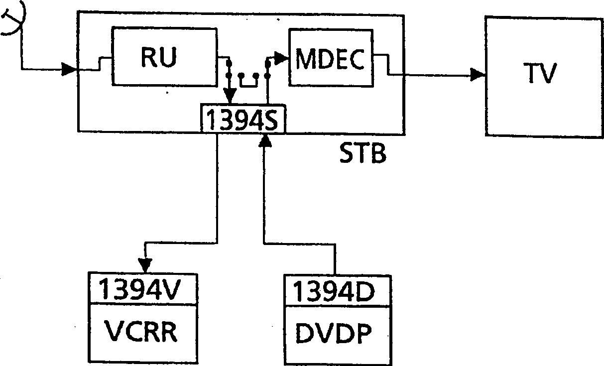
[0037] For example, the present invention can be used in figure 2 In the application shown, a set-top box with a receiving unit RU, an MPEG decoder ...


PUM


Abstract

The IEEE1394 bus communication protocol has three layers: physical layer, link layer, and transaction layer. A link layer IC implements the interface to an external application and prepares data for sending on the bus, or interprets incoming data packets from the IEEE1394 bus. A physical layer IC implements the direct electrical connection to the bus and controls many functions including arbitration for sending data on the bus. The procedure for sending data from a link layer IC onto the bus is that the link layer IC requests access to the bus and then waits until the physical layer IC grants the desired access. Upon detecting the grant status, the link layer IC is free to send data onto the bus. But if in the meantime the link layer IC refrains from sending data onto the bus, the granted bus access will not be given up. As a consequence the bus is blocked for an indefinite time period because the bus access granted cannot be overwritten by the physical layer IC. According to the invention an additional timer function is implemented in the link layer IC. This 'bus grant missed' timer function controls the link layer IC in such a way that it automatically gives back the bus control to the physical layer IC after a predetermined time period has elapsed during which the link layer IC has sent no data onto the bus.

Description

technical field [0001] The invention relates to a method and a device for transferring data on a bus to or from a device to be controlled by said bus. Background technique [0002] The IEEE 1394 bus is a low-cost, high-performance serial bus. It has a read / write memory structure and a very complex communication protocol. It can send data rates of 100, 200 or 400Mbit / s in almost real time. At the same time, data can be sent in both directions. Sending the first 10 bits of the address value corresponds to one of 1023 possible IEEE 1394 bus clusters. Within a particular cluster, the 6 bits following the sending address value correspond to one of 63 nodes to which the application or device is assigned. Data can be exchanged between nodes without interaction from the master controller. The device can be plugged in or disconnected from the network at any time. [0003] The length of the standardized cable used for node connection is 4.5 meters. The cable consists of three tw...

Claims


Application Information

Patent Timeline
Patent Type & Authority Patents(China)
IPC IPC(8): H04L69/40
CPCH04L69/40H04L29/06H04L69/324H04L9/40
Inventor 蒂莫西·海威克劳斯·格特克
Owner THOMSON LICENSING SA
Why Eureka
Try Eureka