
Highway crash barrier

An anti-collision barrier and highway technology, applied in the directions of roads, roads, road signs, etc., can solve the problems of poor cushioning performance of the anti-collision barrier, easy overturning of the anti-collision barrier, and vehicles flying to the roadside, etc., to improve the stability. , The effect of increasing friction and long braking time

Active Publication Date: 2021-06-25
广东宝信达建设有限公司
View PDF5 Cites 1 Cited by
  • Summary
  • Abstract
  • Description
  • Claims
  • Application Information

AI Technical Summary

Problems solved by technology

[0003] When the vehicle is driving on the road, especially at high-speed exits, urban school entrances, unit gates, etc., it is often necessary to set up anti-collision barriers to restrict vehicles. However, the current anti-collision barriers have poor buffer performance and cannot be effective. The anti-collision effect is very good, and the anti-collision barrier is easy to fall over when it is hit by a collision. The vehicle is pressed on the anti-collision barrier and still slides forward and cannot brake effectively, which will easily cause the vehicle to "fly" to the side of the road, causing greater harm to the people on the vehicle. harm

Method used


Image

  • Highway crash barrier
  • Highway crash barrier
  • Highway crash barrier

Examples


Embodiment 1

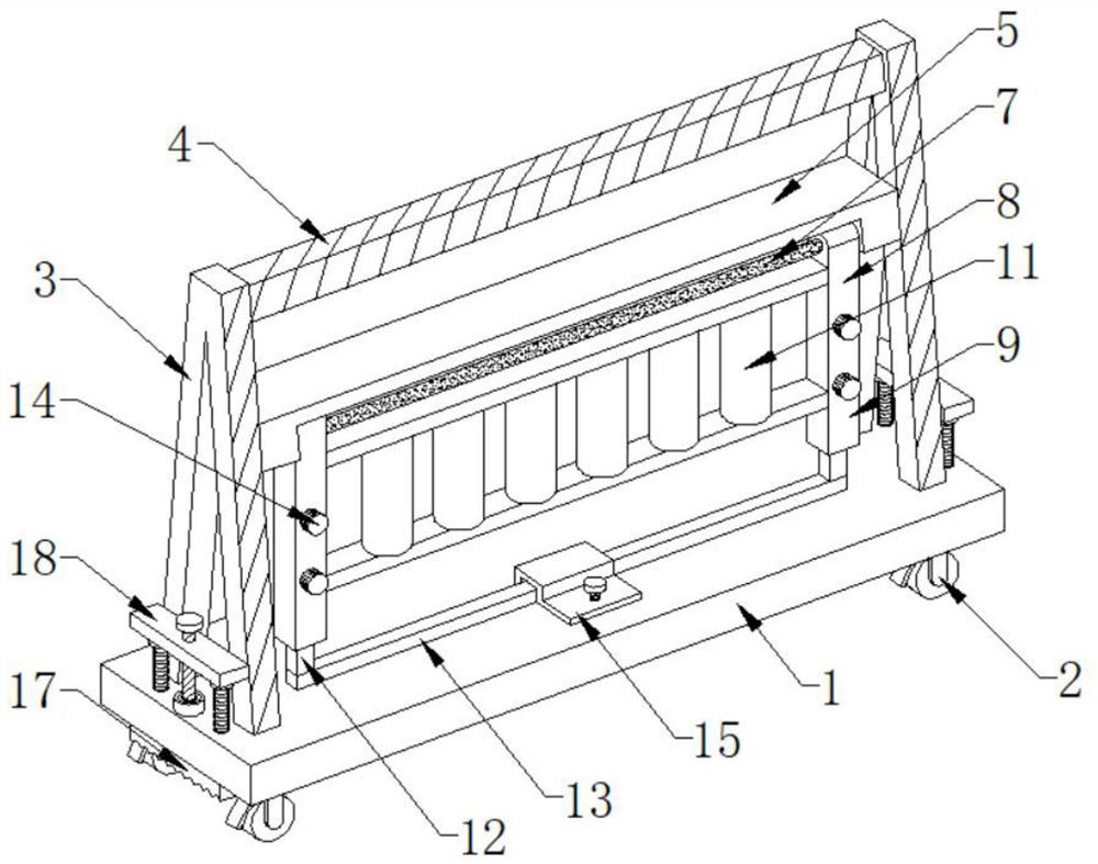
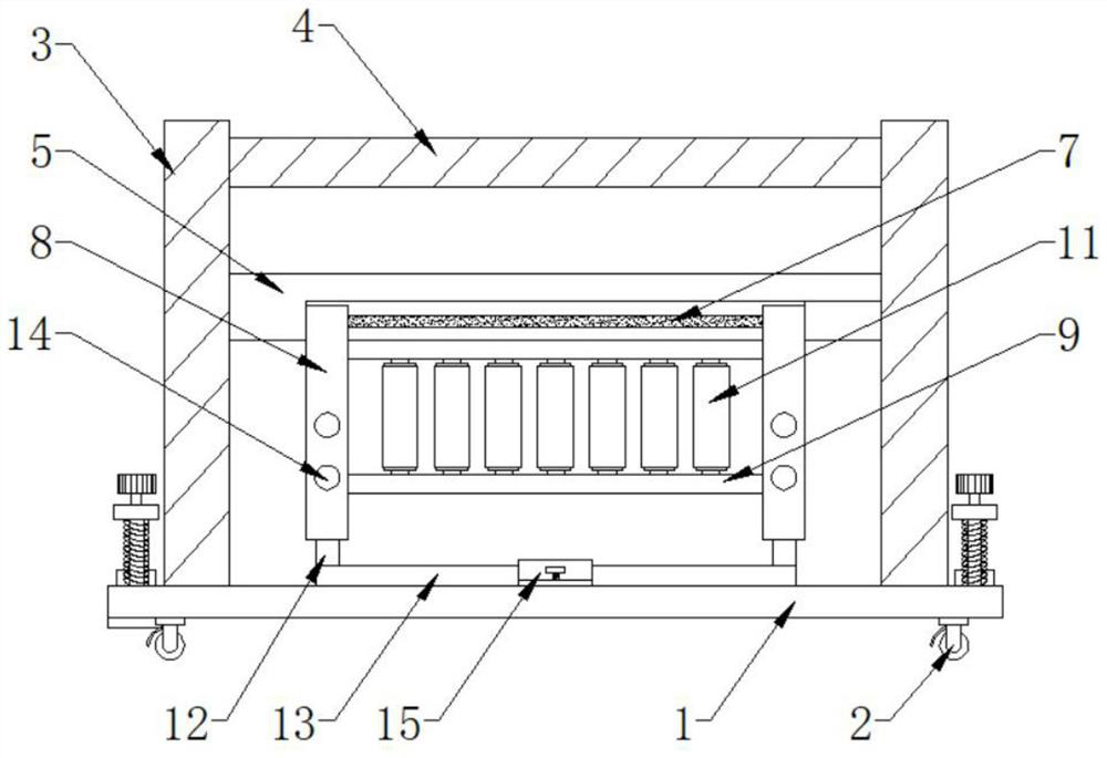
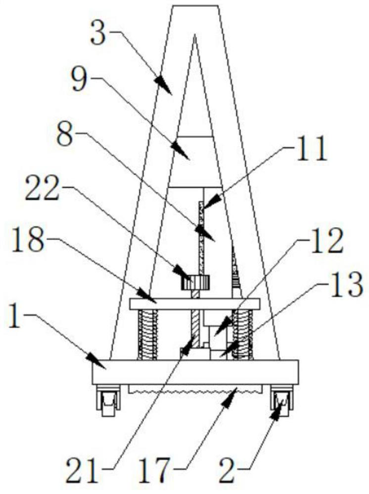
[0025] Such as Figure 1-8 As shown, the present invention provides a highway anti-collision barrier, including a base plate 1, casters 2 are installed at the four corners of the bottom end of the base plate 1, and the casters 2 are equipped with locking buckles, and V-shaped frames are installed on both sides of the top surface of the base plate 1 3. A crossbeam 4 is connected between the tops of the V-shaped frame 3, and the bottom of the crossbeam 4 is provided with a transverse support 5. The bottom side of the transverse support 5 is provided with a container 6, and a rotating rod is embedded in the interior of the container 6. 7. Sleeves 8 are socketed at both ends of the rotating rod 7, and two mutually parallel reinforced cross bars 9 are connected between the sleeves 8, and a plurality of reinforced vertical bars 10 are connected between the reinforced cross bars 9, and the reinforced vertical bars 9 are connected to each other. The outer end surface of the rod 10 is ...


PUM


Abstract

The invention provides a highway crash barrier which comprises a bottom plate, V-shaped frames are installed on the two sides of the surface of the top end of the bottom plate, a cross beam is connected between the top ends of the V-shaped frames, a transverse support is arranged at the bottom of the cross beam, sleeves are connected with the two ends of a rotating rod in a sleeving mode, buffer bodies are movably connected with the surfaces of the outer ends of reinforcing vertical rods in a sleeving mode, extension rods are connected with the interiors of the sleeves in a sleeving mode, abutting rods are connected between the extension rods, a plurality of first locking knobs are arranged on the surfaces of the outer ends of the sleeves, a limiting buckle is arranged in the middle of the surface of the top end of the bottom plate, two supporting rods penetrate through the two sides of the bottom plate, and the bottom ends of the supporting rods are connected with friction plates. According to the highway crash barrier, after the sleeves are rotated outwards, the abutting rods abuts against the ground, the overall side face of the crash barrier is of a triangular structure, when a vehicle collides with the crash barrier, the crash barrier can be prevented from being directly overturned, the vehicle has longer braking time, meanwhile, the buffer bodies absorb force generated when the crash barrier collides with the vehicle head, and damage to the vehicle body is reduced.

Description

technical field [0001] The invention relates to the field of traffic protection, in particular to a highway anti-collision barrier. Background technique [0002] The anti-collision guardrail is an industrial "guardrail", which is mainly used for the protection and protection of equipment and facilities in factories, workshops and warehouses. It is usually made of steel, such as round steel pipe, square steel pipe or profiled steel plate. Highway anti-collision guardrail is the most important traffic infrastructure. my country's expressway was developed in the 1980s. It plays an important role in the development of national economy and society. It is an important maintenance and safety guarantee facility for highways. [0003] When the vehicle is driving on the road, especially at high-speed exits, urban school entrances, unit gates, etc., it is often necessary to set up anti-collision barriers to restrict vehicles. However, the current anti-collision barriers have poor buff...

Claims


Application Information

Patent Timeline
Patent Type & Authority Applications(China)
IPC IPC(8): E01F13/00E01F15/14E01F9/608E01F9/619E01F9/669
CPCE01F13/00E01F15/145E01F15/146E01F9/608E01F9/619E01F9/669
Inventor 温友潭
Owner 广东宝信达建设有限公司
Learn More