Vacuum tube side pressure type exhaust equipment

A technology of exhaust equipment and vacuum tubes, applied in the field of vacuum tubes, can solve problems such as the opening end of the vacuum tube is broken, falling on the top of the air pump, affecting the normal use of the vacuum tube, etc., and achieves the effect of accelerating the pumping speed

Active Publication Date: 2021-06-25
DATANG QITAIHE POWER GENERATION
View PDF9 Cites 2 Cited by
  • Summary
  • Abstract
  • Description
  • Claims
  • Application Information

AI Technical Summary

Problems solved by technology

[0002] The vacuum tube is an important part of the solar water heater. The vacuum tube absorbs solar energy and heats the liquid for use. The inside of the vacuum tube is vacuum-like, and the gas inside the vacuum tube is extracted and discharged by an aspirator, and the open end of the vacuum tube is inserted into the connecting tube. , the air pump extracts the air flow inside the tube body to the exhaust pipe; in the prior art, when the air pump is used to extract the gas inside the vacuum tube, because the connecting tube is at a vertical angle, when the weight of the vacuum tube is large, the vacuum tube is inserted vertically into the When connecting the tube, the open end of the vacuum tube quickly falls down on the top of the air pump and collides with the top of the air pump, which is prone to rupture at the open end of the vacuum tube, which affects the normal use of the vacuum tube

Method used


Image

  • Vacuum tube side pressure type exhaust equipment
  • Vacuum tube side pressure type exhaust equipment
  • Vacuum tube side pressure type exhaust equipment

Examples


Embodiment 1

[0029] as attached figure 1 to attach Figure 5 Shown:

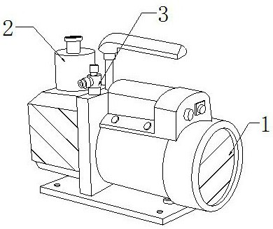
[0030] The present invention provides a vacuum tube side pressure exhaust device, the structure of which includes an air pump 1, a connecting pipe 2, and an exhaust pipe 3, the bottom end of the connecting pipe 2 is vertically fixed on the top of the left end of the air pump 1, and the exhaust pipe 3 Located on the right side of connecting pipe 2.

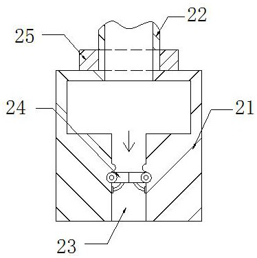
[0031] The connecting pipe 2 includes a pipe body 21, an air inlet pipe 22, an opening 23, an air valve 24, and a buffer mechanism 25. The air inlet pipe 22 is vertically fixed at the top center of the pipe body 21, and the opening 23 runs through the inner center of the pipe body 21. Between the position and the bottom surface, the air valve 24 is installed at the middle and lower position inside the opening 23 , and the buffer mechanism 25 is sleeved outside the bottom end of the intake pipe 22 .

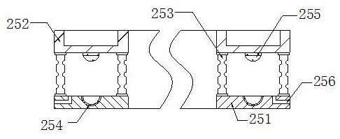
[0032] Wherein, the buffer mechanism 25 includes a support plate 251, a f...

Embodiment 2

[0038] as attached Figure 6 to attach Figure 9 Shown:

[0039] Wherein, the clamping mechanism 52f includes a support plate f1, a clamping plate f2, a push rod f3, and a drainage port f4, the left end of the push rod f3 is fixed on the right side of the support plate f1, and the left side of the clamping plate f2 is It is connected with the right end of the push rod f3, the drainage port f4 runs through between the right side and the upper surface of the support plate f1, and the clamping plate f2 is made of soft rubber material, which is stretchable, which is beneficial for the clamping plate f2 to be received by the opening of the vacuum tube. The different deformation of the outer wall of the end changes, so that the clamping plate f2 is closely attached to the outer wall of the vacuum tube, which can reduce the outside airflow from entering the vacuum tube through the gap between the open end of the vacuum tube and the connecting tube 2 .

[0040] Wherein, the drainage...


PUM


Abstract

The invention discloses vacuum tube side pressure type exhaust equipment. The vacuum tube side pressure type exhaust equipment structurally comprises an air pump, a connecting pipe and an exhaust pipe, the bottom end of the connecting pipe is perpendicularly fixed to the top, close to the left end, of the air pump, the exhaust pipe is located on the right side of the connecting pipe, due to the fact that the opening end of a vacuum tube falls on the top of the air pump rapidly downwards, a buffer mechanism is arranged outside the connecting tube in a sleeved mode, a stress plate moves downwards along with the vacuum tube to buffer the vacuum tube, so that the impact force between the opening end of the vacuum tube and the top of the air pump can be reduced, the phenomenon that the opening end of the vacuum tube is broken is reduced, normal use of the vacuum tube is facilitated, due to the fact that the thickness of the vacuum tube is different, the external air flow easily enters the vacuum tube along the gap between the vacuum tube and a movable groove, a clamping plate of a clamping mechanism is in contact with the outer wall of the vacuum tube, the external air flow can be reduced to enter the vacuum tube along the gap between the movable groove and the vacuum tube, and the air pumping speed of an air exhauster to the vacuum tube can be accelerated.

Description

technical field [0001] The invention belongs to the field of vacuum tubes, and more specifically relates to a vacuum tube side-pressure exhaust device. Background technique [0002] The vacuum tube is an important part of the solar water heater. After absorbing the solar energy through the vacuum tube, the liquid is heated and used. The inside of the vacuum tube is vacuum-like. The gas inside the vacuum tube is extracted and discharged by an air pump, and the open end of the vacuum tube is inserted into the connecting tube. , the air pump extracts the airflow inside the pipe body and discharges it to the exhaust pipe; in the prior art, when the air pump is used to extract the gas inside the vacuum pipe, since the connecting pipe is at a vertical angle, when the weight of the vacuum pipe is large, the vacuum pipe is inserted vertically into the When connecting the tubes, the open end of the vacuum tube quickly falls down on the top of the air pump and collides with the top of...

Claims


Application Information

Patent Timeline
IPC IPC(8): F24S10/40F24S10/70F24S40/48
CPCF24S10/40F24S10/70F24S40/48Y02E10/44
Inventor 许纯敏
Owner DATANG QITAIHE POWER GENERATION
Why Eureka
Try Eureka