Multi-stage type vacuum pumping device and vacuum pumping method thereof

A vacuum device, multi-stage technology, applied in the direction of liquid displacement machinery, machine/engine, mechanical equipment, etc., can solve the problems of energy consumption, energy consumption, waste gas pollution, etc., achieve fast pumping speed, reduce manufacturing cost, security effect

Inactive Publication Date: 2009-05-27
CHIENKUO TECHNOLOGY UNIVERSITY
View PDF5 Cites 1 Cited by
  • Summary
  • Abstract
  • Description
  • Claims
  • Application Information

AI Technical Summary

Problems solved by technology

[0006] 2. A large amount of energy is consumed: because the vacuum device 10 utilizes the steam generated by the steam boiler 14, as described in point 1
When it is necessary to speed up the pumping speed, it is necessary to increase the firepower and provide more heat to increase the steam flow rate. In addition, the vacuum degree requirements of each stage of the process are not necessarily the same. To maintain the applicable vacuum degree, it must be maintained. Sufficient steam flow, all of the above require a lot of energy consumption
[0007] 3. There are safety concerns: because the liquid in the steam boiler 14 is boiled to generate high-temperature and high-pressure steam, which flows quickly in the pipeline unit 15, and the VOD equipment is often used for a long time, when the If the steam boiler 14 is used carelessly or if the pipeline unit 15 is blocked somewhere, it is easy to cause explosion and fire due to excessive pressure, threatening the life and property safety of operators.
[0008] 4. Pollution of the environment: Since the steam boiler 14 is heated by burning a large amount of heavy oil or natural gas to generate a large amount of steam, exhaust gas will inevitably pollute the ambient air during the process, especially when the steam boiler 14 is heated from the cooling furnace at the beginning At this time, a lot of exhaust gas is generated, which seriously affects the air quality

Method used


Image

  • Multi-stage type vacuum pumping device and vacuum pumping method thereof
  • Multi-stage type vacuum pumping device and vacuum pumping method thereof
  • Multi-stage type vacuum pumping device and vacuum pumping method thereof

Examples


Embodiment Construction

[0045] Before the present invention is described in detail, it is noted that in the following description, similar elements are denoted by the same numerals.

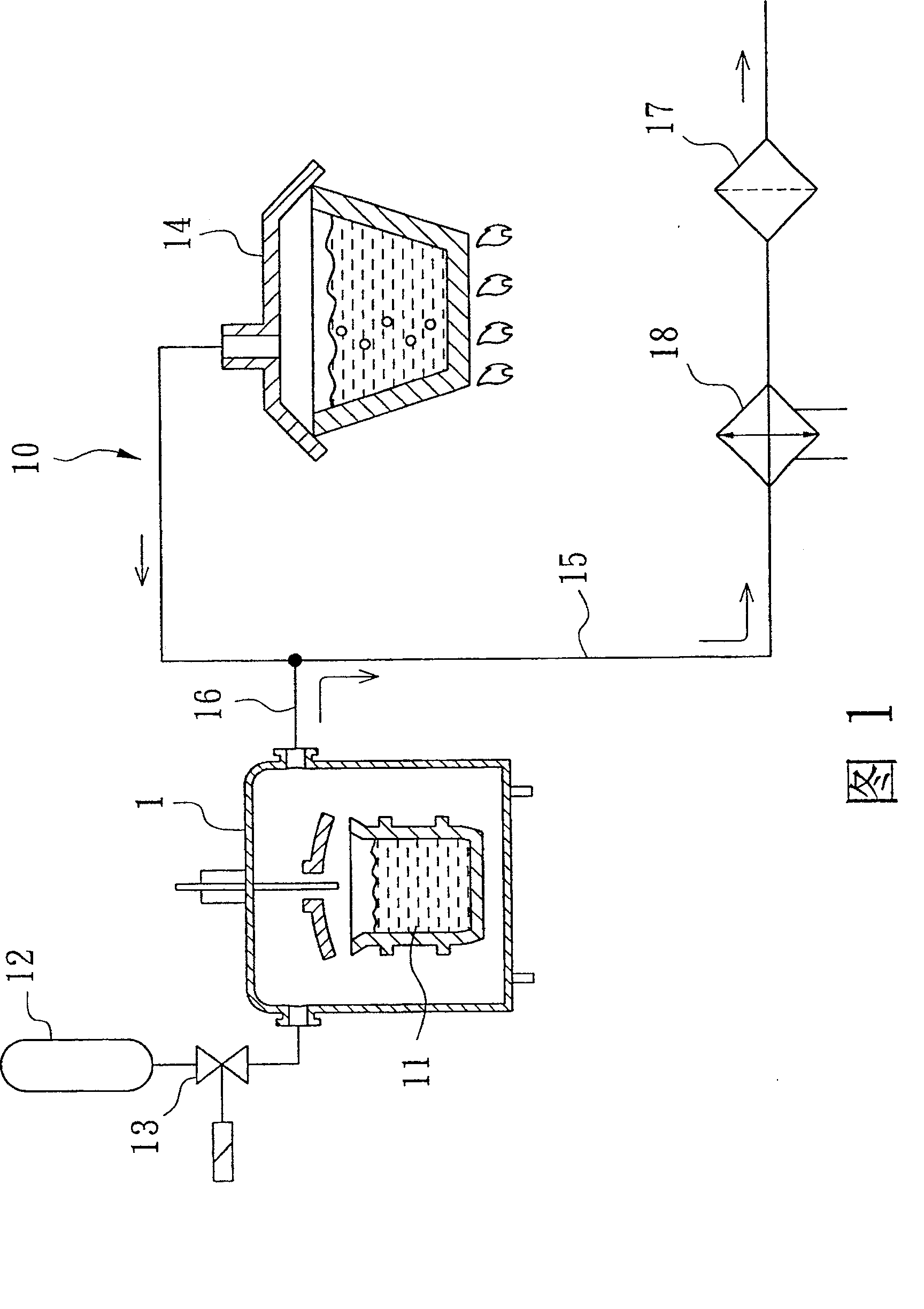
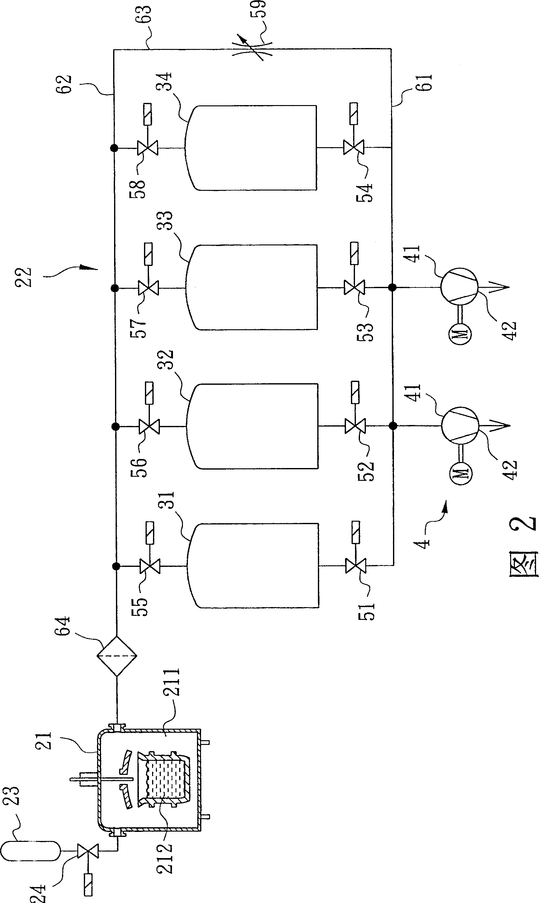
[0046] As shown in Figure 2, a first preferred embodiment of the multistage vacuum pumping device of the present invention can be applied on the VOD refining equipment, and this refining equipment comprises a melting furnace 21, a vacuum device 22 connected to the melting furnace 21, a Connect the gas storage cylinder 23 of the melting furnace 21, and a valve unit 24 for controlling the output gas of the gas storage cylinder 23, wherein the melting furnace 21 has a chamber 211 and is used to store a container filled with molten steel 212 .

[0047] The vacuum device 22 is used to extract the gas in the chamber 211 of the furnace 21 and includes several cavities 31-34, an air extraction unit 4, several first control valves 51-54, and several second control valves 55 ˜58 , a bypass restrictor valve 59 , a first pipeline ...


PUM


Abstract

The present invention relates to a multistage evacuation device and its evacuation method. It is used for quickly reducing pressure in a container. Said evacuation device includes several cavity bodies, an evacuation unit for evacuating gas from every cavity body and reducing pressure in every cavity body interior, a control valve unit which is connected with every cavity body and is used for controlling inlet and outlet of every cavity body and a pipeline unit which is communicated with said control valve unit and evacuation unit.

Description

【Technical field】 [0001] The invention relates to a vacuum pumping device and a vacuum pumping method thereof, in particular to a multistage vacuum pumping device and a vacuum pumping method thereof. 【Background technique】 [0002] As shown in Figure 1, the current vacuum oxygen decarburization (Vacuum OxygenDecarburization, VOD) technology can carry out secondary refining (Secondary Refining) on ​​steel, and the use of vacuum technology can remove the impurity elements contained in molten steel, such as Hydrogen (H), nitrogen (N), sulfur (S), carbon (C)... and other elements and impurities can be degassed to obtain alloy steel with higher purity. The VOD process can be roughly divided into three stages: the first stage, oxygen blowing (Oxygen blowing), the environmental requirement is that the pressure is 1~2×10 4 (N / m2, Pa) and keep it for 30-60 minutes. The second stage, degassing (Degassing), its environment requirement is that the pressure is between 100-500Pa and kep...

Claims


Application Information

Patent Timeline
Patent Type & Authority Patents(China)
IPC IPC(8): F04B37/14C21C7/10
Inventor 徐佳铭
Owner CHIENKUO TECHNOLOGY UNIVERSITY
Why Eureka
Try Eureka